
Network Card User Manual


System Components
Cisco AS5800 Universal Access Server Hardware Installation Guide1-2
System Components
The following sections in this chapter describe the core system components:
• Cisco 5814 Dial Shelf, page 1-8
• Dial Shelf Backplane, page 1-13
• Dial Shelf Field-Replaceable Units
— Dial Shelf Controller Card, page 1-17
— Dial Shelf Filter Module, page 1-27
— Cisco 7206 Router Shelf, page 1-32
— DC-Input Power Specifications, page 1-41
• Power Requirements, page 1-39
The Cisco AS5800 is designed to be rack-mounted. A rack-mount kit is included with each
Cisco 5814 dial shelf and each Cisco 7206 router shelf. Each rack-mount kit provides the hardware
needed to mount the dial shelf and router shelf in a standard, 19-in. equipment rack or standard telco
rack. If you plan to use a 23-in. equipment rack, you must provide your own brackets or shelves to
accommodate the Cisco 7206 router shelf and optional AC power supply. For clearance
requirements and rack-mount installation considerations, refer to the section “Site Specifications” in
the chapter “Preparing for Installation.”
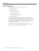
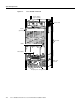
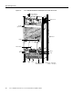
Figure 1-1 shows a front view of a Cisco AS5800, and Figure 1-2 shows a rear view.
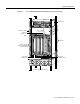
Figure 1-3 shows a front view of a Cisco AS5800 with the enhanced power supply, and Figure 1-4
shows a rear view of a Cisco AS5800 with the enhanced power supply.