
Network Card User Manual

Identifying Startup Problems
Cisco AS5800 Universal Access Server Hardware Installation Guide5-6
• The dial shelf interconnect port adapter link status LED lights.
The link status LED indicates an active connection to the dial shelf and lights when the
interconnect port adapter is receiving a carrier signal from the dial shelf controller card. This
LED should light and remain on when the access server is operating.
If the interconnect port adapter link LED does not light, proceed to the section, “Troubleshooting
the Dial Shelf Interconnect Port Adapter.”
• When all router shelf LEDs light to indicate that the system has booted successfully, the initial
system banner should be displayed on the router shelf console screen. If it is not displayed, verify
that the terminal is set correctly and is properly connected to the I/O controller card console port
as described in the “Connecting to the Router Shelf Console and Auxiliary Ports” section on
page 3-31.
Troubleshooting the Router Installation
Your Cisco 7206 routers went through extensive testing before leaving the factory. However, if you
encounter problems starting the routers, use the information in the chapter “Troubleshooting the
Installation” in the Cisco 7206 Installation and Configuration Guide (Document Number
DOC-7206-ICG=) to help isolate the cause of the problems. Be sure to review the safety warnings
listed in the publication Regulatory Compliance and Safety Information for the Cisco 7200 Series
Routers (Part Number 78-3419-xx) that accompanied your Cisco 7206 before using troubleshooting
procedures.
If you are unable to easily solve the problem, contact a customer service representative for assistance
and further instructions. Be prepared to provide the representative with the following information:
• Date you received the router
• Chassis serial number
• Type of software and release number
• Brief description of the problem you are having
• Brief explanation of the steps you have taken to isolate and resolve the problem
• Maintenance agreement or warranty information
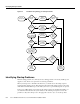
Figure 5-1 shows the general troubleshooting strategy for Cisco 7206 routers. Refer to this chart, as
necessary, to isolate problems to a specific subsystem; then resolve the problem if possible.
Starting Up the Cisco 5814 Dial Shelf
When you first power ON the dial shelf, the following should occur:
• Both PEM power LEDs should light immediately and remain on during normal system operation.
If you are using the AC-input power shelf, both AC-input power supply LEDs should light.
If the green power LEDs do not light, proceed to the section “Troubleshooting the Power
Subsystem.”
• You should hear the fans operating in the blower assembly.
If the fans do not operate, proceed to the section “Troubleshooting the Cooling Subsystems.”
• The LEDs on the dial shelf controller card, modem cards, and trunk cards should light as follows: