
Network Card User Manual

Observing Access Server LEDs
Cisco AS5800 Universal Access Server Hardware Installation Guide4-8
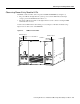
Blower Assembly LEDs
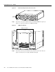
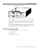
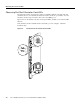
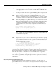
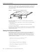
Two LEDs—Power and Fault—are mounted on the blower assembly front panel (see Figure 4-7)
and function as described in Table 4-4.
Figure 4-7 Blower Assembly—Front View
If you detect a problem with the blower assembly LEDs, proceed to Chapter 5, “Hardware
Troubleshooting.”
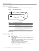
Starting the Cisco 7206
After installing your Cisco 7206 and connecting the cables, start each router as follows:
Step 1 Check for the following:
• Each port adapter is inserted in its slot and its respective port adapter lever is in the
locked position.
• The network processing engine and the I/O controller are inserted in their slots and
their captive installation screws are tightened.
• All network interface cables are connected to the port adapters.
• A Flash memory card is installed in its PCMCIA slot.
• Each power cable is connected and secured with the cable-retention clip.
• The console terminal is turned on.
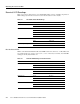
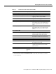
Table 4-4 Blower Assembly Front Panel LEDs
LED Color Description
POWER Green Indicates that all three fans are operating normally. If the power LED is off,
either the blower assembly is not powered on or a fault has been detected in
the blower assembly.
FAIL Yellow Remains off during normal operation. If the fault LED is on, one or more
fans has failed. This failure could be a complete shutdown of one or more
fans, or the blower assembly control card has detected that the speed of one
or more fans has exceeded tolerance levels.
H10989
P
O
W
ER
FA
IL
POWER
LED
FAIL
LED
Cisco AS5800
S
E
R
IE
S