
Network Card User Manual
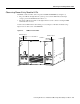

Powering On the Cisco AS5800 and Observing Initial Startup Conditions 4-7
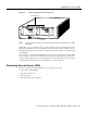
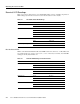
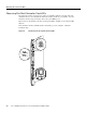
Observing Dial Shelf Controller Card LEDs
Table 4-3 Dial Shelf Controller Card Front Panel LEDs
LED Indicator Display Description
Power and Warning LEDs
PWR (dial shelf controller power) Green Lights when power is ON.
MBUS (system MBus power) Green Lights when the dial shelf controller card is
supplying +5 VDC to the system MBus.
MAJ (major alarm) Yellow Lights to indicate a major
1
alarm condition.
1 A major alarm condition includes router shelf failure, backplane interconnect failure, two-fan failure, power supply failure,
dial shelf card failure, or conditional environmental thresholds.
MIN (minor alarm) Yellow Lights to indicate a minor
2
alarm condition.
2 A minor alarm condition includes modem SIMM failure, HDLC controller failure, trunk line failure, or conditional
environmental thresholds.
ACO (alarm cutoff) Yellow Lights when the alarm cutoff button has been
pressed during a major or minor alarm. Turns off
when the original alarm clears or any new alarm
occurs.
HIST (history clear) Yellow Lights when software recognizes a major or minor
alarm situation. LED powers off when the Clear
Alarm button is pressed and no alarm condition
remains.
Clock and Status LEDs
CLK (clock) Green Lights to identify the dial shelf controller card
active clock; active clock is independent from
master dial shelf controller card designation.
MAST (master) Green Lights to indicate the system software recognizes
the dial shelf controller card is in master mode.
Slot 0 Green Lights when PCMCIA slot 0 is in use.
Slot 1 Green Lights when PCMCIA slot 1 is in use.
DSI (dial shelf interconnect) Green Lights to indicate a working connection between
the dial shelf and router shelf.
10BaseT (Ethernet link) Green Lights to indicate a working data transfer link
connection between the access server and the
system controller.
Liquid Crystal Displays
LCDs (upper and lower) Alphanumeric;
4 characters
each
Displays MSTR to indicate master card.