
Network Card User Manual

Powering On the Cisco AS5800
Cisco AS5800 Universal Access Server Hardware Installation Guide4-2
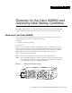
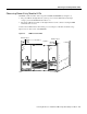
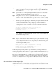
Figure 4-2 Enhanced AC-Input Power Shelf—Front View
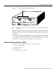
Step 3
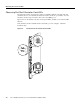
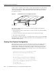
Power ON ( | ) the power switches located on each dial shelf PEM front panel. (See
Figure 4-3.) A green power LED on each PEM should light.
Figure 4-3 PEM Power Switches
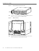
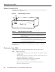
Step 4 Power ON ( | ) the two power switches located on the rear of the router shelf. (See
Figure 4-4.) Both green power supply OK LEDs should light.
22150
AC GOOD
PWR FAIL
PWR GOOD
V OUT
+
-
AC GOOD
PWR FAIL
PWR GOOD
V OUT
+
-
A
C
P
O
W
E
R
A
A
C
P
O
W
E
R
B
Power
switches
H11074
–
4
8
V
–
4
8
V
R
T
N
C
N
C
N
O
P
O
W
E
R
M
IS
W
IR
E
C
N
C
N
O
P
O
W
E
R
M
IS
W
IR
E
–
4
8
V
–
4
8
V
R
T
N
PEM power switches