
Network Card User Manual

CHAPTER
Powering On the Cisco AS5800 and Observing Initial Startup Conditions 4-1
4
Powering On the Cisco AS5800 and
Observing Initial Startup Conditions
This chapter explains how to power on the Cisco AS5800 and confirm normal system startup LED
readings, and then confirm that the proper software is running on the router shelf and dial shelf.
Powering On the Cisco AS5800
After you have installed your dial shelf and router shelf and connected the cables, you are ready to
start up the system by powering on the following components:
• Dial shelf
• AC-input power shelf, if applicable
• Router shelf
Before you power on the Cisco AS5800, you might want to prepare a terminal connection to view
the software startup sequence. See the “Connecting to the Router Shelf Console and Auxiliary Ports”
section on page 3-31 for details on setting up a terminal connection. You should also confirm the
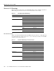
LED indications as shown in the “Observing Access Server LEDs” section on page 4-3.
To power on the system, follow these steps:
Step 1 Power ON the circuit breakers for the circuits the Cisco AS5800 will use.
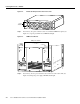
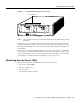
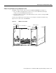
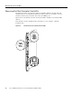
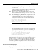
Step 2 If you are using the AC-input power shelf, power ON ( | ) the two power switches located
on the AC-input power shelf front panel. (See Figure 4-1, or Figure 4-2 for the enhanced
power supply.) Four green power OK LEDS should light.
Figure 4-1 AC-Input Power Shelf—Front View
H11098
A
C
1
P
O
W
E
R
2
C
B
2
P
W
R
O
K
F
A
U
L
T
T
E
M
P
I
L
I
M
P
W
R
O
K
F
A
U
L
T
T
E
M
P
I
L
IM
C
B
1
Power
switches