
Network Card User Manual

Installing the Cisco AS5800 3-31
Connecting to the Router Shelf Console and Auxiliary Ports
Connecting to the Router Shelf Console and Auxiliary Ports
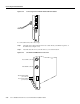
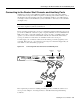
A DCE-mode console port and a DTE-mode auxiliary port are located on the router shelf I/O
controller. The console port is a DB-25 receptacle for connecting a data terminal, which you use to
run the initial setup script and bring up the Cisco AS5800. The auxiliary port is a DB-25 plug for
connecting a modem or other DCE device (such as a CSU/DSU or other router) to the router shelf.
(See Figure 3-26.)
Note Both console and auxiliary ports are asynchronous serial ports; any device connected to these
ports must be capable of asynchronous transmission.
Before connecting a terminal to the console port, configure the terminal to match the router console
port as follows: 9600 baud, 8 data bits, no parity, 2 stop bits (9600 8N2). You need an EIA/TIA-232
DCE console cable to connect the terminal to the console port. After you establish normal router
operation, you can disconnect the terminal. While both the router shelf and the dial shelf have
console ports, functions for both shelves are available from the router console port.
You must supply your own interface cable between the auxiliary port and the equipment you are
connecting. Refer to the Cisco 7206 Installation and Configuration Guide that shipped with your
router shelf for console and auxiliary port pinouts.
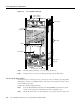
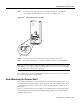
Figure 3-26 Connecting the Router Shelf Console and Auxiliary Ports
This completes the procedures for installing and cabling your Cisco AS5800. To start the access
server, proceed to Chapter 4, “Powering On the Cisco AS5800 and Observing Initial Startup
Conditions.”
Modem
Console terminal
H6539
MII
EN
RJ45
EN
RJ45
LINK
1O PWR
OK
R
J
-
4
5
C
P
U
R
E
S
E
T
FA
ST ETH
ERN
ET IN
PU
T/O
U
TPU
T CO
N
TR
O
LLER
ENABLED
PCMCIA
EJECT
SLOT 0
SLOT 1
FE MII
Auxiliary
port
Console
port