
Network Card User Manual

Connecting the Dial Shelf to the Router Shelf
Cisco AS5800 Universal Access Server Hardware Installation Guide3-26
Note To install the Cisco 7206 router shelf, refer to the Cisco 7206 Installation and Configuration
Guide that shipped with your Cisco 7206 router shelf. After you complete the router shelf
installation, you are ready to connect the cables. Proceed to the following section “Connecting the
Dial Shelf to the Router Shelf.”
Note It is possible to use two routers in a split dial shelf configuration with a single 5814 dial shelf.
Install the second router shelf above the first.
Connecting the Dial Shelf to the Router Shelf
The Cisco 7206 router shelf contains a dial shelf interconnect port adapter with a single RJ-45
receptacle, which is used to connect the router shelf to the Cisco 5814 dial shelf. The interconnect
port adapter installs in any 7206 router shelf port adapter slot and connects directly to the Cisco 5814
dial shelf controller card using a single full-duplex cable.
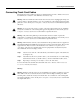
The cable used for this connection is available only from Cisco Systems. It is customized with
shielding to decrease electromagnetic interference (EMI) emissions, and jackscrews to secure the
connection. You must use this specially designed cable, which shipped with your interconnect port
adapter, to connect the dial shelf to the router shelf. For detailed cabling specification information,
refer to Appendix A, “Cisco AS5800 Specifications.” If the cable was not shipped, contact CCO as
described in the“Cisco Connection Online” section on page xiv.
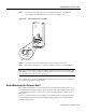
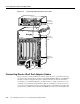
Figure 3-21 shows the dial shelf interconnect cable with jackscrew connectors.
Figure 3-21 Dial Shelf Interconnect Cable
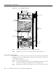
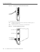
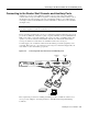
Figure 3-22 shows the RJ-45 receptacle on the dial shelf interconnect port adapter.
Figure 3-22 Dial Shelf Interconnect Port Adapter Front Panel
H11100
H11101
ENABLED
L
IN
K
DIAL SHELF INTERCONNECT ADAPTER
ENABLED LED LINK LED
RJ-45 port