
Network Card User Manual

Installing the Cisco AS5800 3-25
Rack-Mounting the Router Shelf
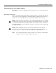
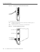
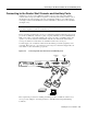
Step 3 Connect the power cable stripped wires to the DC terminal block on the PEM and
securely tighten the terminal block connector screws. (See Figure 3-20.)
Figure 3-20 DC Terminal Block on the PEM
Step 4
Connect the other end of your DC power cables to your DC power source.
Step 5 Repeat Step 1 through Step 4 to connect your DC power cables to the second PEM.
Note If the two DC conductors entering the PEM terminal block are reversed, a red warning LED
on the PEM goes on to indicate a miswire. No damage will occur; however, you must power OFF
the power at the source and reverse the connections.
This completes the procedure for installing the dial shelf in a rack. You are now ready to install the
Cisco 7206 router shelf in the equipment rack.
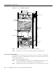
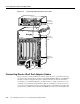
Rack-Mounting the Router Shelf
The router shelf is intended to be rack-mounted above the dial shelf in the same rack; however, you
can rack-mount the router shelf in an adjacent rack. The interconnect cable supplied by Cisco, which
provides the physical connection between the router shelf and the dial shelf, is available in 6-ft or
20-ft lengths.
There is no clearance requirement for mounting the router shelf directly above the dial shelf. Use the
rack-mounting brackets and cable-management kit that shipped with the Cisco 7206 router shelf to
install the router in the rack.
C
N
C
N
O
P
O
W
E
R
M
IS
W
IR
E
–
4
8
V
–
4
8
V
R
T
N
–48V
–48V
RTN
DC terminal block
H11575