
Network Card User Manual

Connecting Cables to the Dial Shelf
Cisco AS5800 Universal Access Server Hardware Installation Guide3-24
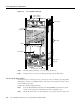
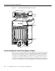
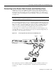
Figure 3-19 Cisco AS5800—Rear View
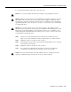
Step 2
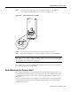
Attach the double ground lug to your own 6-gauge ground wire.
Step 3 Using the screws you removed, fasten the ground lug to the dial shelf chassis.
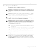
Connecting DC Power Cables
If your site has access to a DC power source, you need to provide your own DC power cables. In the
United States you need to use 6 AWG stranded or solid copper wire; elsewhere use 16 mm
2
solid or
10 mm
2
stranded copper wire.
Complete the following cabling instructions:
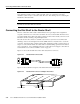
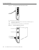
Step 1 Locate the DC terminal block located on the dial shelf PEM front panel and loosen the
connector screws using a 1/4-in. flat-blade screw driver. (See Figure 3-20.)
Step 2 Strip the DC power cable of its outer insulation to expose about 1/2-inch of copper wires.
–
4
8
V
–
4
8
V
R
T
N
C
N
C
N
O
POW
ER
MISWIRE
H11450
–
4
8
V
–
4
8
V
R
T
N
C
N
C
N
O
PO
WER
M
ISW
IRE
N
E
T
W
O
R
K
P
R
O
C
E
S
S
I
N
G
E
N
G
I
N
E
-
1
5
0
Safety cover
not shown
Router shelf
Dial shelf
Filter module
Double
ground lug
PEMs
Power switches
(to boot system)
AC-input power shelf (optional)