Cisco AS5800 Universal Access Server Hardware Installation Guide Corporate Headquarters Cisco Systems, Inc. 170 West Tasman Drive San Jose, CA 95134-1706 USA http://www.cisco.
THE SPECIFICATIONS AND INFORMATION REGARDING THE PRODUCTS IN THIS MANUAL ARE SUBJECT TO CHANGE WITHOUT NOTICE. ALL STATEMENTS, INFORMATION, AND RECOMMENDATIONS IN THIS MANUAL ARE BELIEVED TO BE ACCURATE BUT ARE PRESENTED WITHOUT WARRANTY OF ANY KIND, EXPRESS OR IMPLIED. USERS MUST TAKE FULL RESPONSIBILITY FOR THEIR APPLICATION OF ANY PRODUCTS.
CONT ENT S About This Guide vii Document Objectives Audience vii vii Document Organization viii Document Conventions Safety Warnings ix viii Terms and Acronyms x Related Documentation xi If You Need More Information Cisco Connection Online Chapter 1 xiv Cisco AS5800 Product Overview System Components 1-2 Functional Overview 1-7 xiii 1-1 Cisco 5814 Dial Shelf 1-8 Clock Management 1-9 Dial Shelf OIR Events 1-10 Dial Shelf Card Bootup 1-10 Slot Ownership Arbitration 1-11 Hub Redundancy 1-1
Power Requirements 1-39 AC-Input Power Shelf 1-39 Standard AC-Input Power Shelf LED Indicators DC-Input Power Specifications 1-41 AC-Input Power Specifications 1-41 Enhanced AC-Input Power Shelf 1-42 Online Insertion and Removal Chapter 2 Preparing for Installation 1-40 1-43 2-1 Site Requirements 2-1 AC and DC Power 2-1 Cisco 5814 Dial Shelf 2-3 Cisco 7206 Router Shelf 2-4 Lifting Safety 2-4 Required Tools and Equipment 2-5 Preparing the Dial Shelf for Rack-Mount 2-6 Removing the Blower Assembly 2-
Connecting the AC Power Cables 3-15 Grounding the AC-Input Power Shelf to the Dial Shelf 3-15 Connecting the DC Power Cables 3-17 Connecting the Monitor Cable 3-18 Connecting the AC Power Cords 3-20 Installing the Safety Cover on the Standard Power Shelf 3-21 Connecting to a DC Power Source 3-23 Grounding the Dial Shelf 3-23 Connecting DC Power Cables 3-24 Rack-Mounting the Router Shelf 3-25 Connecting the Dial Shelf to the Router Shelf 3-26 Connecting Router Shelf Port Adapter Cables 3-28 Connecting
Troubleshooting the Network Processor Card 5-12 Troubleshooting the Port Adapters 5-12 Troubleshooting the Dial Shelf Interconnect Port Adapter Troubleshooting the Dial Shelf Processor Subsystem 5-13 Troubleshooting the Dial Shelf Controller Card 5-13 Troubleshooting the Dial Shelf Cards 5-14 Troubleshooting Network Interfaces Appendix A Cisco AS5800 Specifications 5-12 5-14 A-1 System Specifications A-1 Backplane Specifications A-3 Blower Assembly Specifications A-4 Dial Shelf Controller Card Specific
About This Guide This section discusses document objectives, targeted audience, document organization, document conventions, terms and acronyms, and additional documentation available. Document Objectives This document describes the initial site preparation, hardware installation, and troubleshooting of the Cisco AS5800 universal access server (Cisco AS5800), which consists of the Cisco 5814 dial shelf and the Cisco 7206 router shelf.
Document Organization Document Organization The Cisco AS5800 Universal Access Server Hardware Installation Guide is organized as follows: • Chapter 1, “Cisco AS5800 Product Overview,” provides an overview of the access server, describes its features, and lists its physical specifications. • Chapter 2, “Preparing for Installation,” includes safety recommendations, site preparation instructions, and instructions for preparing the Cisco 5814 dial shelf for rack mounting.
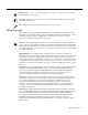
Caution Means reader be careful. In this situation, you might do something that could result in equipment damage or loss of data. 12 9 3 Timesaver Means the action described saves time. You can save time by performing the action described in the paragraph. 6 Tips Means the following information might help you solve a problem. Safety Warnings Safety warnings appear throughout this publication in procedures that, if performed incorrectly, might harm you. A warning symbol precedes each warning statement.
Terms and Acronyms Avvertenza Questo simbolo di avvertenza indica un pericolo. La situazione potrebbe causare infortuni alle persone. Prima di lavorare su qualsiasi apparecchiatura, occorre conoscere i pericoli relativi ai circuiti elettrici ed essere al corrente delle pratiche standard per la prevenzione di incidenti.
• Double-density modem module (DMM)—Each double-density modem card contains 12 DMM SIMMS. Each DMM SIMM contains 12 digital modems.The Cisco AS5800 has the capability of terminating up to 1,344 modem connections when equipped with 10 double-density modem cards and 2 CT3 trunk cards. • Egress interface—The router shelf interface to a network, such as the Internet or a corporate intranet or backbone. Supported interfaces include Fast Ethernet, HSSI, FDDI, and ATM interfaces.
Related Documentation Table 1 Related and Referenced Documents Cisco Product Document Title Cisco AS5800 • Read Me First • Cisco AS5800 Universal Access Server Hardware Installation Guide (this book) • Cisco AS5800 Universal Access Server Dial Shelf Card Guide • Cisco AS5800 Universal Access Server Software Installation and Configuration Guide (to be replaced later this year by the Cisco AS5800 Universal Access Server Operations, Administration, Maintenance, and Provisioning Guide) • Cisco AS5800 Univ
If You Need More Information For information regarding the Cisco AS5800 that is beyond the scope of this document or for additional information, use the following resources: • For Cisco AS5800 software configuration, refer to the Cisco AS5800 Universal Access Server Software Installation and Configuration Guide that shipped with your system.
Cisco Connection Online — Cisco IOS Software Command Summary — Cisco Management Information Base (MIB) User Quick Reference Cisco Connection Online Cisco Connection Online (CCO) is Cisco Systems’ primary, real-time support channel. Maintenance customers and partners can self-register on CCO to obtain additional content and services. Available 24 hours a day, 7 days a week, CCO provides a wealth of standard and value-added services to Cisco’s customers and business partners.
CHAPT ER 1 Cisco AS5800 Product Overview The Cisco AS5800 is a high-density, ISDN and modem WAN aggregation system that provides both digital and analog call termination. It is intended to be used in service provider dial point-of-presence (POP) or centralized enterprise dial environments. The access server components include a Cisco 5814 dial shelf and a Cisco 7206 router shelf. Two versions of an optional AC power shelf is also available, either standard or enhanced.
System Components System Components The following sections in this chapter describe the core system components: • • • Cisco 5814 Dial Shelf, page 1-8 Dial Shelf Backplane, page 1-13 Dial Shelf Field-Replaceable Units — Dial Shelf Controller Card, page 1-17 — Dial Shelf Filter Module, page 1-27 — Cisco 7206 Router Shelf, page 1-32 — DC-Input Power Specifications, page 1-41 • Power Requirements, page 1-39 The Cisco AS5800 is designed to be rack-mounted.
System Components Figure 1-1 Cisco AS5800—Front View 5 2 RX ETHERNET-10BFL TX RX 0 TX RX 1 TX RX 2 TX RX TX 3 4 1 3 0 EN 2 3 ENA LIN 3 K 1 0 BLE D 6 Router shelf ETHERNET 10BT 4 D LE TC RD RC 2 LIN K EN LB CD FAST ETHERNET AB TC RD RC LB CD 1 TD TD TC RD RC CD TD LB EN TD TC RD RC LB CD FAST SERIAL 1 AB LE OT M II FAST ETHERNET INPUT/OUTPUT CONTROLLER FE 0 SL EN D PC M A CI EC EJ T 0 SL FE LE AB OT EN NK LI FE CP POWE
System Components Figure 1-2 Cisco AS5800—Rear View Power switches (to boot system) Router shelf NETWORK PROCESSING ENGINE-150 Double ground lug Dial shelf PEMs POWER POWER MISWIRE MISWIRE Filter module –48V –48V RTN C NC NO –48V –48V RTN C NC NO AC-input power shelf (optional) 1-4 Cisco AS5800 Universal Access Server Hardware Installation Guide H11450 Safety cover not shown
System Components Figure 1-3 Cisco AS5800 with Enhanced AC-Input Power Shelf—Front View 5 2 RX ETHERNET-10BFL TX RX 0 TX RX 1 TX RX 2 TX RX TX 3 4 1 3 0 EN 2 3 ENA LIN 3 K 1 0 BLE D 6 Router shelf ETHERNET 10BT 4 D LE TC RD RC 2 LIN K EN LB CD FAST ETHERNET AB TC RD RC LB CD 1 TD TD TC RD RC CD TD LB EN TD TC RD RC LB CD FAST SERIAL 1 AB LE OT M II FAST ETHERNET INPUT/OUTPUT CONTROLLER FE 0 SL EN D PC M CI A EJ EC T 0 SL
System Components Figure 1-4 Cisco AS5800 with Enhanced AC-Input Power Shelf—Rear View Power switches (to boot system) Router shelf NETWORK PROCESSING ENGINE-150 Double ground lug Dial shelf PEMs POWER POWER MISWIRE MISWIRE Filter module –48V –48V RTN C NC NO –48V –48V RTN C Black Red NC NO 24520 Red Black –48V return + 1-6 –48V input – AC-input power shelf (optional) Cisco AS5800 Universal Access Server Hardware Installation Guide Note: Red = –48V return Black = –48V input
Functional Overview Functional Overview The Cisco AS5800 is a high-density, ISDN and modem WAN aggregation system that provides both digital and analog call termination. It is intended to be used in service-provider dial point-of-presence (POP) or centralized-enterprise dial environments. The dial shelf cards and the host router shelf communicate over a nonblocking interconnect that supports 100-Mbps full-duplex service.
Cisco 5814 Dial Shelf On the DSC card, only one common logic is active at any one time, which is identified by the CLK (clock) LED on the DSC card front panel. The active common logic is user selectable and is independent from each dial shelf controller card. This assures that if a DSC card needs replacing or if the slave DSC card becomes the master, clocking remains stable. The selected common logic should not be changed during normal operation, unless related hardware failure is suspected or diagnosed.
Cisco 5814 Dial Shelf can be mapped to any HDLC controller or modem module. You can install multiple ingress interface cards of like or different types, which enables you to configure your systems as fully operative, port redundant, or card redundant, depending on your specific needs. Figure 1-5 shows the Cisco 5814 dial shelf, fully loaded.
Cisco 5814 Dial Shelf Only one common logic is active at any one time, which is identified by the clock (CLK) LED on the DSC’s front panel. The active common logic is user-selectable and is independent from each DSC. This assures that if a DSC needs replacing or if the slave DSC becomes the master, clocking remains stable. The selected common logic should not be changed during normal operation, unless related hardware failure is suspected or diagnosed.
Cisco 5814 Dial Shelf The first time a router shelf sends an inventory response to the DSC, it includes a flag indicating that all dial shelf cards should be reloaded. In split mode, the final dial shelf card image is downloaded by each DSC from the router shelf that owns it. Slot Ownership Arbitration The DSCs communicate between themselves to determine which one is to be active, where “being active” implies being the master for all the dial shelf card slots.
Dial Shelf Field-Replaceable Units Environmental Monitoring In split mode, environmental monitoring for the full dial shelf is carried out by both DSCs. This means that warnings about overheating cards go to both router shelves, regardless of which one owns the card (or even if neither claims ownership of the card). Sending the warnings to both routers reduces the chance of an environmental problem going unreported.
Dial Shelf Backplane Dial Shelf Backplane The Cisco AS5800 is equipped with a field-replaceable backplane module, which is designed to meet critical safety, isolation, and electromagnetic compatibility (EMC) requirements. The Cisco 5814 dial shelf backplane includes 14 slots that seat the ingress trunk cards, the modem cards, and the dial shelf controller cards. Figure 1-6 shows the Cisco 5814 dial shelf with no cards installed, as viewed from the system front.
Dial Shelf Field-Replaceable Units Figure 1-7 Cisco 5814 Dial Shelf Backplane—Rear View Blower assembly connector H11278 Dial shelf backplane Power studs The dial shelf backplane first receives –48 VDC power from the DC-input power supplies by way of the filter module, and the power is then distributed throughout the dial shelf. The DC PEMs connect to the backplane using four blind-mating 1.25-in. power studs, which are located near the bottom of the backplane.
Dial Shelf Blower Assembly Dial Shelf Blower Assembly The blower assembly in the Cisco 5814 dial shelf monitors the dial shelf internal operating temperatures and maintains acceptable cooling parameters. The blower assembly contains three variable-speed impeller fans and a controller card that performs the following functions: • Monitors internal temperatures The controller card contains temperature sensors, which monitor internal air temperature within the dial shelf chassis.
Dial Shelf Field-Replaceable Units Figure 1-8 Cisco 5814 Dial Shelf with Blower Assembly Installed—Front View POWER LED FAIL Captive LED Captive screw Blower assembly screw POWER FAIL SERIES T MA R DE DE MS MS PW IN T T IN MA R R MA MS DE MO CALLS CALLS J CALLS MA CALLS MA CALLS MO MO DE DE MS MS MS DE MO CALLS MO CALLS MO CALLS MO MO DE DE MS MS MS DE MO CALLS PW PW IN T T R R IN MA MA PW PW IN T T IN R R PW MA PW MA IN T T R R IN MA
Dial Shelf Controller Card Dial Shelf Controller Card The dial shelf controller card is the main processor card for the dial shelf, and it performs the following functions: • Links the dial shelf to the router shelf, where data is transferred as Ethernet packets encapsulated in proprietary protocol • Interconnects trunk cards and modem cards A backplane interconnect concentrator on each dial shelf controller card connects to each dial shelf card installed in the dial shelf.
Dial Shelf Field-Replaceable Units Figure 1-9 shows the dial shelf controller card components.
Dial Shelf Controller Card Figure 1-10 shows the front view of the Cisco 5814 dial shelf with two dial shelf controller cards installed.
Dial Shelf Field-Replaceable Units Figure 1-11 shows the dial shelf controller card front panel LEDs.
Dial Shelf Controller Card Table 1-3 describes the dial shelf controller front panel LEDs and LCDs. Table 1-3 Dial Shelf Controller Front Panel LEDs and LCDs LED Indicator Display Description PWR (dial shelf controller power) Green Lights when power is ON. MBUS (system MBus power) Green Lights when the dial shelf controller card is supplying +5 VDC to the system MBus. MAJ (major alarm) Yellow Lights to indicate a major1 alarm condition.
Dial Shelf Field-Replaceable Units Figure 1-12 shows the dial shelf controller card front panel push buttons, and Table 1-4 describes push button actions.
Dial Shelf Controller Card Figure 1-13 shows the dial shelf controller card front panel ports, and Table 1-5 describes the port functions.
Dial Shelf Field-Replaceable Units Table 1-5 Dial Shelf Controller Card Front Panel Ports Port Description Console Provides RJ-45 connection to the system controller console port for system management. Network clock Provides BNC connection for an external T1 or E1 reference input signal from which a clock is extracted. Alarms Provides DB-15 serial connection to an external audio or visual alarm source. 10BaseT For Cisco internal use only.
Dial Shelf DC-Input Power Supply • System environmental monitoring A 10-pin connector monitors system environmental status and communicates this status from each PEM to the filter module maintenance bus (MBus). Table 1-6 lists connector pins supporting system status signals.
Dial Shelf Field-Replaceable Units • Bell alarm signaling The PEMs provide relay outputs for standard central office bell alarms. These bell alarm contacts are available on a terminal plug mounted on the PEM front panel. • Online insertion and removal (OIR) The PEMs support OIR, which means that you can remove or replace a PEM while the system is operating; system operation is not affected. The PEMs are located on either side of the filter module below a removable rear cover.
Dial Shelf Filter Module Dial Shelf Filter Module The Cisco AS5800 is equipped with a passive DC power filter in the dial shelf, which contains a broadband electromagnetic interference (EMI) filter and circuitry for monitoring power coming into the dial shelf. The DC power filter is housed in the filter module, which resides in the dial shelf between the two PEMs.
Dial Shelf Field-Replaceable Units Figure 1-15 Filter Module—Dial Shelf Rear View Back cover POWER POWER MISWIRE MISWIRE PEM –48V RTN C NC NO –48V –48V RTN C NC NO H10993 –48V Filter module For detailed specification tables, refer to Appendix A, “Cisco AS5800 Specifications.
Enhanced AC-Input Power Shelf Enhanced AC-Input Power Shelf The enhanced AC-input power shelf includes two 2,000-watt (W) AC-input power supplies that plug into a common power backplane in the enhanced AC-input power shelf. A single AC-input power supply is capable of powering a fully configured Cisco 5814 dial shelf. A second power supply provides full redundancy.
Dial Shelf Field-Replaceable Units Cisco AS5800 Enhanced AC-Input Power Shelf—Rear View 24518 Figure 1-17 AC-input power receptacles BUS BUS + terminal terminal stud stud (-48 volt return) (-48 volt input) Ground post (chassis ground does not connect to +/- studs) For detailed specification tables, refer to Appendix A, “Cisco AS5800 Specifications.
Enhanced AC-Input Power Shelf Enhanced Power Shelf LED Indicators The enhanced AC-input power shelf includes two inputs that are located on the left front of the power shelf and three LEDs that are located on the front of each power supply for the enhanced AC-input power shelf (See Figure 1-25.
Cisco 7206 Router Shelf Cisco 7206 Router Shelf This section provides physical and functional overviews of the Cisco 7206 router shelves. It contains physical descriptions of the router hardware and major components and functional descriptions of hardware-related features.
Cisco 7206 Router Shelf Network Interfaces Network interfaces reside on port adapters that provide the connection between the router’s three peripheral component interconnect (PCI) buses and external networks. The Cisco 7206 has six slots (slots 1 to 6) for the port adapters, one slot for an Input/Output (I/O) controller, and one slot for a network processing engine (NPE). You can place port adapters in any of the six available slots.
Cisco 7206 Router Shelf Figure 1-20 Port Adapter Slot Numbering Port adapter slot 6 Port adapter slot 4 Port adapter slot 2 Blank port adapter 3 2 1 0 6 TOKEN RING 5 FAST ETHERNET 4 K RJ4 0 LIN MII 5 D LE AB EN 0 TX 2 RX 4 TX RX 3 TX RX 2 TX 1 RX TX EN ETHERNET-10BFL CD LB RC RD TC TD CD LB RC RD TC TD CD LB RC RD TC TD CD LB RC RD TC TD EN FAST SERIAL RX 3 3 2 2 1 0 LINK 1 0 3 EN AB LE D ETHERNET 10BT R ES ET H6422 O PW K R 1O 5 R L J4
Cisco 7206 Router Shelf Cisco 7206 Router—Rear View Chassis grounding receptacles Internal fans Power supply filler plate AC-input receptacle H6423 Figure 1-21 NETWORK PROCESSING ENGINE-150 Network processing engine or network services engine AC-input power supply Power switch Three internal fans draw cooling air into chassis and across internal components to maintain an acceptable operating temperature. The three fans are enclosed in a tray that is located in the subchassis.
Cisco 7206 Router Shelf Rack-Mount Kit A rack-mount kit is included with all Cisco 7206 routers when they are shipped from the factory. The kit provides the hardware needed to mount the router in a standard 19-in. equipment rack or a telco rack. The steps for installing a Cisco 7206 router in an equipment rack are explained in the Cisco 7206 Installation and Configuration Guide (Document Number DOC-7206-ICG=).
Dial Shelf Interconnect Port Adapter • Chassis To replace the chassis you must remove all internal components. When replacing the chassis, refer to the individual configuration notes that explain how to remove and replace each internal component. • Flash memory cards Detailed instructions for removing and replacing Flash memory cards and SIMMs are contained in the configuration note Memory Replacement Instructions for the Network Processing Engine and Input/Output Controller (Part Number 78-3226-xx).
Split Dial Shelves The following conditions must be met before the dial shelf interconnect port adapter is enabled: • The dial shelf interconnect port adapter is correctly connected to the router shelf midplane and receiving power. • • A valid Cisco IOS software image for the adapter has been downloaded successfully. The system recognizes the adapter. If any of the above conditions are not met, or initialization fails for other reasons, the enabled LED remains off.
Power Requirements Power Requirements The Cisco AS5800 ships configured for either AC-input or DC-input power with loadsharing, depending on your order. AC-Input Power Shelf The AC-input power shelf includes two 2,000W AC-input power supplies that plug into a common power backplane in the AC-input power shelf. A single AC-input power supply is capable of powering a fully configured Cisco 5814 dial shelf. A second power supply provides full redundancy.
Power Requirements Cisco AS5800 Standard AC-Input Power Shelf—Rear View BUS H11038 Figure 1-24 BUS + BUS terminal stud Ground post to BUS + terminal stud Ground post BUS + terminal stud AC-input power receptacles Standard AC-Input Power Shelf LED Indicators The standard AC-input power shelf includes two LEDs that are located on the left front of the power shelf and four LEDs that are located on the front of each power supply. (See Figure 1-25.
DC-Input Power Specifications Table 1-9 Standard AC-Input Power Supply LEDs (continued) LED Color Description TEMP Yellow Lights when the power shelf has shut down because of overtemperature conditions. I LIM Yellow Lights when the power shelf is overloaded and operating in a current-limiting state. The current limit LED lights for either of the following reasons: • The power supply is operating in a current overload condition, such that the voltage is drawn below the fault threshold level.
Power Requirements Each AC-input power supply is powered on by a separate power switch, which is located on the AC-input power shelf front panel. (See Figure 1-23.) Ejector levers with locking spring clips secure each power supply to the backplane connectors, and a handle on each power supply allows you to remove and replace the power supplies with ease. The AC-input power shelf is three rack-units high (5.25 in. [13.3 cm]) and rack-mounts in a standard 19-in.
Online Insertion and Removal The enhanced AC-input power shelf is three rack units high [5.25 in. (13.32 cm)], and mounts underneath the dial shelf in a standard 19-in., 4-post or telco-type rack assembly. All cable connections for AC-input power, DC-output power, and status signals are made from the enhanced AC-input power shelf rear. (See Figure 1-27.) Two modular power cables connect each AC-input power supply to the site AC-input power source.
Online Insertion and Removal Each DSC card and dial shelf card contains female connectors that connect to the system backplane. Each male backplane connector comprises a set of tiered pins in three lengths. The backplane pins send specific signals to the system as they make contact with the card connectors. The system assesses the signals it receives and the order in which it receives them to determine whether to initialize a startup or shutdown procedure.
CHAPT ER 2 Preparing for Installation This chapter describes the equipment and site requirements for installing the Cisco AS5800. Before installing your access server, you should consider the power and cabling that must be in place at your installation site, the equipment needed for installation, and the environmental conditions your installation site must meet to maintain normal operation. This chapter guides you through the installation preparation process.
Site Requirements Figure 2-1 AC Power Planning Optional components Circuit 1 Circuit 2 Cisco 3640 SC 120 VAC 15A 5A 5A 5A Cisco DPS 200 Cisco 7206 router shelf Cisco 7206 router shelf 120 VAC 15A 5A 5A 5A Cisco 5814 dial shelf DC power to dial shelf AC input power shelf Core components Circuit 4 220 VAC 20A 29095 Circuit 3 220 VAC 20A If AC power will be used, to provide full redundancy the Cisco AS5800 requires two 220 VAC 30A circuits for the Cisco 5814 dial shelf and its components, an
AC and DC Power Figure 2-2 DC Power Planning Optional components Circuit 1 Circuit 2 Cisco 3640 SC -48 VDC 40A 8-13A 8-13A 8-13A Cisco DPS 200 Cisco 7206 router shelf Cisco 7206 router shelf -48 VDC 40A 8-13A 8-13A 8-13A Circuit 3 -48 VDC 50A Core components Circuit 4 -48 VDC 50A 29096 Cisco 5814 dial shelf If DC power will be used, to provide full redundancy the Cisco AS5800 requires two DC power circuits providing up to 54A at -48VDC for theCisco 5814 dial shelf and its components, and
Lifting Safety Cisco 7206 Router Shelf The Cisco 7206 router shelf can be ordered with either 280W AC-input or 280W DC-input power supplies. • The AC-input power supply uses a power factor corrector that allows the Cisco 7206 router shelf to operate on input voltage and frequency within the ranges of 100 to 240 VAC and 50/60 Hz. • Each AC-input power supply operating at 120 VAC requires a minimum of 5A service. We recommend powering the Cisco 7206 router shelf from a 15A receptacle at the power source.
Required Tools and Equipment Warning Two people are required to lift the chassis. Use the handles on the chassis sides. To prevent injury, keep your back straight and lift with your legs, not your back. To prevent damage to the chassis and components, never attempt to lift the chassis with the handles on the power supplies, the filter module, or on the blower assembly. These handles are not designed to support the weight of the chassis.
Preparing the Dial Shelf for Rack-Mount The rack-mount kit includes the following parts: • • • Six rack-mount brackets for mounting the dial shelf in the rack • A total of 16 slotted 10-32 x 3/8 screws for rack installation Two support brackets A total of 12 M5 x 10-mm Phillips flathead screws to secure the rack-mount brackets to the dial shelf In addition, you might need the following external equipment, especially when installing a split dial shelf configuration: • • • Data service unit (DSU) to
Removing the Blower Assembly Step 4 Place your other hand under the blower assembly as it extends from the dial shelf chassis. Step 5 Slowly pull the blower assembly all the way out of the slot and set it aside until you are ready to reinstall it.
Preparing the Dial Shelf for Rack-Mount Removing the DC Power-Entry Modules To remove the DC PEMs, complete the following steps: Step 1 Using a 1/4-inch flat-blade screwdriver, loosen the captive screws on the PEM front panel. Step 2 Grasp the handle and carefully pull the PEM from the backplane connectors using a gentle rocking motion; then remove the PEM from the DC power supply chassis. (See Figure 2-4.
Removing Dial Shelf Cards and Dial Shelf Controller Cards Removing Dial Shelf Cards and Dial Shelf Controller Cards To remove the dial shelf cards and dial shelf controller cards, follow these steps: Caution Trunk cards and modem cards weigh 8 lb (3.3 kg) each. Dial shelf controller cards weigh 8.5 lb (3.8 kg) each. Use two hands when removing or replacing cards in the dial shelf. Step 1 Record the original position of each card before you remove the cards from the dial shelf slots.
Preparing the Dial Shelf for Rack-Mount CALLS R MAI NT R MAI NT CALLS MO MO DE DE MS MS PW R MAI NT MS DE MO CALLS CALLS MAJ CALLS PW R MAI NT MS DE MO MO MO DE DE MS MS MS MO DE DE DE MS MS MS DE PU FC MO MO MO CALLS PW R MAI NT PW R MAI NT PW PW PW PW R MAI NT R MAI NT R MAI NT PW PW PW FR T1 CALLS MAJ R# TO NI MO CU ALARM ALARM LA 75 ALARM R R EA EA CL CL NL LM OO P RA FF FF TO LM ST ST HI HI TO FC T1 PU FR MIN O O CU HC
Installing the Rack-Mount Brackets on the Chassis Installing the Rack-Mount Brackets on the Chassis Bracket placement depends on the type of rack you use to install your access server. This section describes both a 4-post rack installation and a telco rack installation. Threaded holes on the chassis sides are strategically located to position and mount bracket hardware. The dial shelf also has a mounting flange in front for flush-front mounting.
Installing the Rack-Mount Brackets on the Chassis Mounting Forward Brackets for an Offset Telco Rack Installation To install the forward rack-mount brackets on the dial shelf for an offset telco rack-mount configuration, complete the following steps: Step 1 Locate the forward upper and lower threaded holes on the right side of the chassis. (See Figure 2-7, positions a and b.
Plant Wiring Plant Wiring The following are guidelines for setting up the plant wiring and cabling at your site. When planning the location of the new system, consider the distance limitations for signaling, EMI, and connector compatibility, as described in the following sections. Interference Considerations When wires are run for any significant distance in an electromagnetic field, interference can occur.
Safety Recommendations When preparing your site for network connections to the access server, you should consider the following: • Type of cabling required (fiber, thick or thin coaxial, shielded twisted-pair, or unshielded twisted-pair) • • • Distance limitations • Cable pinouts (if you plan to build your cables) Cables needed for interface connections Any additional interface equipment needed, such as transceivers, hubs, switches, modems, channel service units (CSUs), or data service units (DSUs)
Maintaining Safety with Electricity Maintaining Safety with Electricity The Cisco 5814 dial shelf cards, dial shelf controller cards, and power supplies are designed to be removed and replaced while the system is operating, without causing damage to the system. When working with the Cisco 7206 router shelf, however, you must power down the system before removing or replacing the I/O controller and network processing engine.
Rack-Mounting Considerations Preventing Electrostatic Discharge Damage Electrostatic discharge (ESD) damage, which occurs when electronic cards or components are improperly handled, can result in complete or intermittent system failures. The access server components include printed circuit boards that are fixed in metal carriers. These metal carriers provide electromagnetic interference (EMI) shielding, connectors, ejector levers, or handles to protect against ESD.
Rack-Mounting Considerations Note One rack unit (1.75 in. or 4.4 cm) is the maximum distance between the dial shelf and the AC-input power shelf that accommodates the required safety cover. Some equipment racks provide a power strip along the length of one of the mounting strips. If your rack has a power strip, consider the position of the strip when planning fastener points to ensure that you will be able to slide dial shelf cards and dial shelf controller cards straight out of their respective slots.
Rack-Mounting Considerations • Install the forward rack-mount brackets (if needed for your rack configuration) before you install the dial shelf in the rack; then install the rear brackets. • Install the dial shelf in an open rack whenever possible. If installation in a cabinet is unavoidable, ensure that the cabinet has adequate ventilation. Caution To prevent the dial shelf from overheating, never install your Cisco AS5800 in a cabinet or room that is not properly ventilated or air conditioned.
Rack-Mounting Considerations Figure 2-10 Cisco 5814 Footprint and Outer Dimensions 17.5 in. (44.5 cm) Chassis width Front 19 in. (48.3 cm) Chassis width (including mounting flange) H11039 23.5 1n. ( 59.7 cm) Chassis depth Rear Caution To prevent the rack from tipping when installing the router in telco racks, ensure that the rack is bolted to the floor and, if necessary, anchored with appropriate fixtures.
Rack-Mounting Considerations Site Specifications Table 2-1 lists the operating and nonoperating environmental site requirements. The following ranges are those within which the access server will continue to operate; however, a measurement that is approaching the minimum or maximum of a range indicates a potential problem. You can maintain normal operation by anticipating and correcting environmental anomalies before they approach the maximum operating range.
CHAPT ER 3 Installing the Cisco AS5800 This chapter explains the procedures for installing the access server.
Connecting to an AC Power Source This section explains how to attach the power cables and rack-mount the AC-input power shelf. For detailed cabling specification tables, refer to Appendix A, “Cisco AS5800 Specifications.
Installing the Power Shelf in the Rack Cables Mounted on the Rear of the AC Power Shelf Monitor cable Black Ground Red 29094 Figure 3-1 Red BUS — terminal stud BUS Black + terminal stud Installing the Power Shelf in the Rack You install the power shelf in the rack by securing the permanent mounting flanges to two posts or mounting strips in the rack using the slotted mounting screws provided.
Connecting to an AC Power Source Figure 3-2 Removing and Replacing a Power Supply PWR OK CB 2 FAULT TEMP AC 1 POWER 2 PWR OK I LIM TEMP I LIM CB 1 H11156 FAULT Step 4 Grasp the power supply handle and pull the power supply halfway out of the bay. Then with your other hand under the power supply to support it, pull the power supply completely out of the bay. Step 5 Repeat Step 1 through Step 4 for the other power supply.
Installing the Power Shelf in the Rack Removing and Replacing an Enhanced Shelf Power Supply 22152 Figure 3-3 AC POWER A AC POWER B AC GOOD PWR FAIL + PWR GOOD V OUT AC GOOD PWR FAIL V OUT + PWR GOOD - 1 2 Step 4 Grasp the power supply handle and pull the power supply halfway out of the bay. Then with your other hand under the power supply to support it, pull the power supply completely out of the bay. Step 5 Repeat Step 1 through Step 4 for the other power supply.
Connecting to an AC Power Source Figure 3-4 illustrates the standard AC-input power shelf installed in a 4-post rack. Figure 3-4 Installing the AC-Input Power Shelf in a 4-Post Rack PWR OK CB 2 PWR OK FAULT FAULT AC 1 POWER 2 TEMP TEMP I LIM I LIM H11160 CB 1 Installing the Dial Shelf in the Rack One person can not install the dial shelf chassis in the rack unassisted. Two or preferably three people will be needed.
Installing the Dial Shelf in the Rack Step 4 Figure 3-5 Lift and slide the dial shelf chassis into the rack, resting it on the two support brackets. Push it back until the forward brackets or chassis mounting flanges meet the mounting strips or posts on both sides of the equipment rack. When the chassis is slid back all the way, keep one or two people holding the chassis in place using the handles, or gripping the chassis where the DC PEMs belong.
Connecting to an AC Power Source Mounting the Rear Brackets This section explains how to mount the rear brackets for telco and 4-post rack installations. Note You must mount the rear brackets after you install the dial shelf in the rack.
Mounting the Rear Brackets Figure 3-6 Cisco 5814 Dial Shelf Installed in a Telco Rack Forward upper bracket (a) Center lower bracket (c) Support brackets H11597 Forward lower bracket (b) This completes the dial shelf rack-mounting procedures for a telco rack. Proceed to the section “Replacing the Dial Shelf Components.
Replacing the Dial Shelf Components Figure 3-7 Cisco 5814 Dial Shelf Installed in a 4-Post Rack Dial shelf H11043 Support bracket This completes the dial shelf rack-mounting procedures for a 4-post rack. Proceed to the following section “Replacing the Dial Shelf Components.” Replacing the Dial Shelf Components This section contains instructions for replacing the dial shelf components.
Replacing the Blower Assembly Replacing the Blower Assembly Replace the blower module in the dial shelf as follows: Caution The blower assembly weighs 27.5 lb (12.5 kg). Use two hands when removing or replacing the blower assembly. Step 1 Place one hand on the blower assembly handle and place your other hand under the blower assembly. (See Figure 3-8.
Replacing the Dial Shelf Components Replacing the Power-Entry Modules To reinstall the PEMs, complete the following steps. (Refer to Figure 3-9 to locate the PEMs in the dial shelf.) Step 1 Grasp the PEM handle and carefully align the PEM with the DC-input power supply bay. Step 2 Slide the PEM into the power supply bay until it is fully seated and connected to the backplane connectors. Step 3 Using a 1/4-inch flat-blade screwdriver, tighten the captive screws on the PEM front panel.
Replacing the Dial Shelf Cards and Dial Shelf Controller Card Replacing the Dial Shelf Cards and Dial Shelf Controller Card Replace the trunk cards, modem cards, and dial shelf controller cards in the chassis as follows: 12 9 3 6 Timesaver Your dial shelf arrived with trunk cards, modem cards, and dial shelf controller cards installed in the proper slots.
Replacing the Dial Shelf Components Figure 3-10 Using the Ejector Levers PW R MA IN T PW R MA IN T MO DE MS NL R OO ALM P LA LM MO NIT OR # CALLS 75 NL R OO ALM P LA LM MO NIT OR # HCPU H11097 HCPU 75 FC T PU 1FR FC T PU 1FR FC T PU 1FR PW R MA IN T PW R MA IN T FC T PU 1FR Step 4 HCPU E1FR E1FR HCPU E1FR E1FR PW R MA IN T Panel fastener 0 HCPU Seat the card in the backplane by pushing the card firmly until the ejector levers fold in toward the trunk card front panel and th
Connecting Cables to the Dial Shelf Connecting Cables to the Dial Shelf Once the dial shelf has been rack-mounted and all components have been reinstalled into the dial shelf, DC power connections from a DC source or AC-input power shelf can be connected to the dial shelf. The monitor connection from an AC-input power shelf should also be connected at this stage. The following sections assume the use of the optional AC-input power shelf.
Connecting Cables to the Dial Shelf Figure 3-11 Attaching the Ground Wire to a Standard Power Shelf Filter module POWER POWER MISWIRE MISWIRE PEM –48V RTN C NC NO –48V –48V RTN C NC NO H11676 –48V 3-16 Cisco AS5800 Universal Access Server Hardware Installation Guide
Connecting the AC Power Cables Figure 3-12 Attaching the Ground Wire to an Enhanced Power Shelf Filter module POWER POWER MISWIRE MISWIRE PEM –48V RTN C NC NO –48V –48V RTN C NC NO 24603 –48V This completes the ground cable installation. Connecting the DC Power Cables For detailed cabling specification information, refer to Appendix A, “Cisco AS5800 Specifications.
Connecting Cables to the Dial Shelf Figure 3-13 Connecting the DC-Interconnect Cables PEM –48V NC NO –48V –48V RTN C NC NO –48V RTN DC terminal block Monitor cable Black Step 4 C Ground Hex nut Red BUS — terminal stud Red BUS Black + terminal stud Fit the exposed wire end of the black insulated cable into the DC terminal block labeled –48V on each PEM and securely tighten the terminal block connector screws. Repeat for the other PEM.
Connecting the AC Power Cables Figure 3-14 Connecting the Monitor Cable Filter module POWER POWER MISWIRE MISWIRE PEM –48V –48V RTN C NC NO –48V –48V RTN C NC NO DB-9 cable connector H11161 DB-25 cable connector AC-input power shelf Installing the Cisco AS5800 3-19
Connecting Cables to the Dial Shelf Figure 3-15 Connecting the Monitor Cable to an Enhanced Power Shelf Filter module POWER POWER MISWIRE MISWIRE PEM –48V –48V RTN C NC NO –48V –48V RTN C NC NO DB-9 cable connector 24601 DB-25 cable connector (alarm port) AC-input power shelf This completes the monitor cable installation. You must now connect the AC-input power cords.
Connecting the AC Power Cables Caution Do not plug the AC-input power shelf into the same power source as the router shelf or into the power strip on your equipment rack. The 20A connectors on the AC-input power shelf are incompatible with the power source used for the router shelf and with the 15A power strips used in most equipment racks.
Connecting Cables to the Dial Shelf Caution The safety cover is an integral part of the product. Do not operate the standard AC power shelf without the safety cover installed. Operation of the unit without the safety cover in place will invalidate the safety approvals and pose a risk of fire and electrical hazards. Warning The device is designed to work with TN power systems.
Connecting to a DC Power Source Connecting to a DC Power Source The following sections are for installations using a direct DC power source, without an AC-input power shelf. Grounding the Dial Shelf The Cisco 5814 dial shelf ships with a double ground lug attached to two pemnuts in the upper left corner on the rear of the dial shelf chassis. For detailed cabling specification information, refer to Appendix A, “Cisco AS5800 Specifications.
Connecting Cables to the Dial Shelf Figure 3-19 Cisco AS5800—Rear View Power switches (to boot system) Router shelf NETWORK PROCESSING ENGINE-150 Double ground lug Dial shelf PEMs POWER POWER MISWIRE MISWIRE Filter module –48V –48V RTN C NC NO –48V –48V RTN C NC NO AC-input power shelf (optional) H11450 Safety cover not shown Step 2 Attach the double ground lug to your own 6-gauge ground wire. Step 3 Using the screws you removed, fasten the ground lug to the dial shelf chassis.
Rack-Mounting the Router Shelf Step 3 Connect the power cable stripped wires to the DC terminal block on the PEM and securely tighten the terminal block connector screws. (See Figure 3-20.) Figure 3-20 DC Terminal Block on the PEM POWER –48V –48V –48V RTN C NC NO H11575 MISWIRE –48V RTN DC terminal block Step 4 Connect the other end of your DC power cables to your DC power source. Step 5 Repeat Step 1 through Step 4 to connect your DC power cables to the second PEM.
Connecting the Dial Shelf to the Router Shelf Note To install the Cisco 7206 router shelf, refer to the Cisco 7206 Installation and Configuration Guide that shipped with your Cisco 7206 router shelf. After you complete the router shelf installation, you are ready to connect the cables. Proceed to the following section “Connecting the Dial Shelf to the Router Shelf.” Note It is possible to use two routers in a split dial shelf configuration with a single 5814 dial shelf.
Connecting the Dial Shelf to the Router Shelf To connect the dial shelf interconnect cable, follow these steps: Caution Do not use the dial shelf interconnect port adapter for outgoing WAN connections. Warning Hazardous network voltages are present in WAN ports regardless of whether power to the unit is OFF or ON. To avoid electric shock, use caution when working near WAN ports. When detaching cables, detach the end away from the unit first.
Connecting Router Shelf Port Adapter Cables Figure 3-23 Connecting the Dial Shelf Interconnect Cable RX ETHERNET-10BFL TX RX TX 0 RX 1 TX RX 2 TX RX TX 3 4 1 3 0 EN 2 3 EN LIN 3 K 0 1 AB 2 LED 6 5 ETHERNET 10BT 4 Dial shelf interconnect port adapter D LE AB RD RC FAST ETHERNET 2 LI NK EN LB CD RD RC LB CD TD 1 TC TC TC RD LB CD TD TD RC EN TD TC RD RC LB CD FAST SERIAL 1 II M FAST ETHERNET INPUT/OUTPUT CONTROLLER FE 0 T O SL D LE AB
Connecting Trunk Card Cables Connecting Trunk Card Cables The trunk card provides 12 RJ-45 receptacles for channelized E1 or T1 lines, or BNC connectors for T3 trunk lines. To connect T1 or E1 trunk lines, follow these steps: Warning The telecommunications lines must be disconnected 1) before unplugging the main power connector and/or 2) while the housing is open.
Connecting Trunk Card Cables Figure 3-24 Connecting the CT1 and CE1 Trunk Card RJ-45 Cables 9 10 O N 11 TM O N R M RJ-45 cable H11105 CHANNELIZED E1/T1 To connect the T3 lines, follow these steps: Step 1 Attach the end of the T3 transmit and receive cables directly to the BNC receptacles on the trunk card (see Figure 3-25). Step 2 Attach the network end of your CT3 cables to your external network.
Connecting to the Router Shelf Console and Auxiliary Ports Connecting to the Router Shelf Console and Auxiliary Ports A DCE-mode console port and a DTE-mode auxiliary port are located on the router shelf I/O controller. The console port is a DB-25 receptacle for connecting a data terminal, which you use to run the initial setup script and bring up the Cisco AS5800. The auxiliary port is a DB-25 plug for connecting a modem or other DCE device (such as a CSU/DSU or other router) to the router shelf.
Connecting to the Router Shelf Console and Auxiliary Ports 3-32 Cisco AS5800 Universal Access Server Hardware Installation Guide
CHAPT ER 4 Powering On the Cisco AS5800 and Observing Initial Startup Conditions This chapter explains how to power on the Cisco AS5800 and confirm normal system startup LED readings, and then confirm that the proper software is running on the router shelf and dial shelf.
Powering On the Cisco AS5800 Enhanced AC-Input Power Shelf—Front View 22150 Figure 4-2 AC POWER A Power switches AC POWER B AC GOOD PWR FAIL + PWR GOOD V OUT AC GOOD PWR FAIL V OUT Step 3 + PWR GOOD - Power ON ( | ) the power switches located on each dial shelf PEM front panel. (See Figure 4-3.) A green power LED on each PEM should light.
Observing Access Server LEDs Figure 4-4 Router Shelf Power Switches—Rear View H11572 Power switches NETWORK PROCESSING ENGINE-150 Step 5 Listen for fans in both the router shelf and the dial shelf. You should hear them operating immediately. During the boot process, the LEDs on most of the port adapters in the router shelf and on the dial shelf cards and dial shelf controller cards light on and off in irregular sequence while the system is running initial self-diagnostic tests.
Observing Access Server LEDs Nominal LED Readings Table 4-1 provides a quick reference for nominal LED readings for Cisco AS5800 components. If LED readings vary from those listed, refer to the relevant sections for more details.
Observing Power-Entry Module LEDs Observing Power-Entry Module LEDs The PEMs contain two LEDs on the front panel—POWER and MISWIRE. (See Figure 4-5.) • The power LED should light when the system is powered on. The LED indicates that input voltage is present and the PEM circuit breaker is on. • The miswire LED should remain off, but lights when the two DC conductors entering the PEM terminal block are reversed.
Observing Access Server LEDs Observing Dial Shelf Controller Card LEDs The dial shelf controller card front panel contains several LEDs. Unlike the other dial shelf cards installed in the Cisco 5814 dial shelf, the dial shelf controller card has two power LEDs, one for the dial shelf controller card power and the other for the system MBus power. Figure 4-6 shows the dial shelf controller card front panel LEDs, and Table 4-3 describes the LED functions.
Observing Dial Shelf Controller Card LEDs Table 4-3 Dial Shelf Controller Card Front Panel LEDs LED Indicator Display Description PWR (dial shelf controller power) Green Lights when power is ON. MBUS (system MBus power) Green Lights when the dial shelf controller card is supplying +5 VDC to the system MBus. MAJ (major alarm) Yellow Lights to indicate a major1 alarm condition. MIN (minor alarm) Yellow Lights to indicate a minor2 alarm condition.
Observing Access Server LEDs Blower Assembly LEDs Two LEDs—Power and Fault—are mounted on the blower assembly front panel (see Figure 4-7) and function as described in Table 4-4. Figure 4-7 Blower Assembly—Front View FAIL LED POWER LED FAIL Cisco AS5800 Table 4-4 SERIES H10989 POWER Blower Assembly Front Panel LEDs LED Color Description POWER Green Indicates that all three fans are operating normally.
Starting the Cisco 7206 Step 2 At the rear of the router, place the power switch on the power supply in the ON (|) position. Repeat this if a second power supply is installed. The green OK LED on the power supply goes on. Step 3 Listen for the fans; you should immediately hear them operating. If not, immediately place the power switch on the power supply in the OFF (0) position and proceed to the “Troubleshooting the Router Installation” section on page 5-6.
Viewing Your System Configuration Unique to the Cisco AS5800 is the interconnect port adapter that installs in the router shelf. The dial shelf interconnect contains two LEDs: an enabled LED and a link status LED, shown in Figure 4-8. After system initialization, the enabled LED lights to indicate that the dial shelf interconnect has been enabled for operation.
Viewing Your System Configuration Cisco Internetwork Operating System Software IOS (tm) 7200 Software (C5800-p4-mz), 12.0(19970915:09303] Copyright (c) 1986-1999 by Cisco Systems, Inc. Compiled Mon 01-Dec-99 06:00 by Imagetext-base: 0x600088C0, data-base: 0x60940000 ROM: System Bootstrap, Version 12.0(4)XJ [dschwart 10], RELEASE SOFTWARE (fc1) Cisco 7206 (NPE200) processor with 57344K/8192K bytes of memory. R4700 processor, Implementation 33, Revision 1.
Viewing Your System Configuration Step 3 View the router Cisco IOS release, dial shelf controller image, and boot image: 5800# sh ver Cisco Internetwork Operating System Software IOS (tm) 5800 Software (C5800-P4-M), Version 12.0(4)XJ TAC:Home:SW:IOS:Specials for info Copyright (c) 1986-1999 by Cisco Systems, Inc. Compiled Thu 12-Aug-99 13:16 by ayeh Image text-base: 0x60008900, data-base: 0x611A6000 ROM: System Bootstrap, Version 12.0(19990210:195103) [12.
Where to Go Next DA-Slot12 uptime is 24 minutes System returned to ROM by power-on System image file is "slot0:dsc-c5800-mz.120-4.XJ1.bin" Cisco c5800 (R4K) processor with 24576K/8192K bytes of memory. R4700 CPU at 150Mhz, Implementation 33, Rev 1.0, 512KB L2 Cache Last reset from power-on 1 Ethernet/IEEE 802.3 interface(s) 2 Dial Shelf Interconnect(DSI) FE interface(s) 123K bytes of non-volatile configuration memory. 8192K bytes of Flash PCMCIA card at slot 0 (Sector size 128K).
Where to Go Next 4-14 Cisco AS5800 Universal Access Server Hardware Installation Guide
CHAPT ER 5 Hardware Troubleshooting Your Cisco AS5800 was thoroughly tested before leaving the factory. If you encounter problems initializing system startup, use the information in this chapter to help isolate the cause.
Problem Solving with Subsystems Problem Solving with Subsystems The key to problem solving is isolating the problem to a specific subsystem. The first step in solving startup problems is to compare what the system is doing to what it should be doing. Try to isolate the problem to one of the following three router shelf or dial shelf subsystems: • • • Power Cooling Processor Start by checking the router shelf power components.
Problem Solving with Subsystems—Cisco 7206 Router Dial shelf processor cards include the following: • • • Dial shelf controller card Modem cards Trunk cards The following sections will help you isolate a problem within one of these subsystems and direct you to the appropriate troubleshooting section. Problem Solving with Subsystems—Cisco 7206 Router The key to solving problems with the system is isolating the problem to a specific subsystem.
Identifying Startup Problems Figure 5-1 Turn on system power Troubleshooting Strategy for Startup Problems DC OK LED on ? Troubleshoot power subsystem No DC OK LED on ? Yes Fans operating ? Yes Troubleshoot cooling subsystem No Fans operating ? No Yes Yes Reseat NPE-G1 and restart Check system state with I/O controller LEDs or I/O controller LEDs OK? No No NPE-G1 LEDs OK? or Reseat I/O controller and restart Yes I/O No controller LEDs OK? Yes Check system state with port adapter LEDs
Starting Up the Cisco 7206 Router Shelf Note Although an overtemperature condition is unlikely at initial startup, the environmental monitoring functions are included in this chapter because these functions also monitor internal voltages.
Identifying Startup Problems • The dial shelf interconnect port adapter link status LED lights. The link status LED indicates an active connection to the dial shelf and lights when the interconnect port adapter is receiving a carrier signal from the dial shelf controller card. This LED should light and remain on when the access server is operating. If the interconnect port adapter link LED does not light, proceed to the section, “Troubleshooting the Dial Shelf Interconnect Port Adapter.
Troubleshooting the Power Subsystems — Dial shelf controller card—Powers ON first, followed by remaining logic cards. The PWR and MBus LEDs should light. The remaining four alarm LEDs should all briefly flash on and then turn off. If the MBus LED remains off but the power LED is on, there might be a problem with the MBus power supply on the card. Replace the card. — Trunk card—At initial power ON, all LEDs light while the system runs a series of diagnostics.
Troubleshooting the Power Subsystems Router Shelf Power Subsystem In the router shelf, check the following to help isolate a problem with the power subsystem: • Is the power OK LED on? — If yes, the power source is good and the power supply is functional. — If no, verify that the power cable is connected at both ends. If the power OK LED remains off and the power switch is set correctly, suspect the power source or the power cable.
Troubleshooting the Cooling Subsystems — Verify that the overtemperature LED is off. If a power supply overtemperature LED lights, verify that the ambient temperature is below 120°F (50 °C) and the air intake is not blocked. If the condition persists, replace the power supply. — Verify that the current limit LED is off. If a power supply current limit LED lights, verify that the DC bus terminals on the AC-input power shelf rear are not short-circuited and a supported dial shelf configuration is being used.
Troubleshooting the Cooling Subsystems Dial Shelf Cooling Subsystem In the dial shelf, check the following to help isolate a problem with the cooling system: • Do the blower assembly fans operate? To determine whether the dial shelf fans are operating, listen for them. In noisy environments, place your hand under the exhaust vents on the back of the dial shelf blower assembly to feel for air being forced out the vents.
Troubleshooting the Processor Subsystems Troubleshooting the Processor Subsystems The processor subsystem consists of the I/O controller card, network processor card, and all port adapters in the router shelf, and the dial shelf controller card, modem cards, and trunk cards in the dial shelf. The following sections contain specific troubleshooting information for each of these components. The router shelf I/O controller card and network processor card are required system components.
Troubleshooting the Processor Subsystems • Is the FE ENABLED LED on? — If yes, the Fast Ethernet port on the I/O controller is initialized and enabled for operation. — If the FE enabled LED remains off at system startup, there is probably a problem with the Fast Ethernet port on the I/O controller.
Troubleshooting the Dial Shelf Processor Subsystem — If power is supplied to the router shelf but the enabled LED remains off, the system has detected a hardware failure. You need to replace the interconnect port adapter. • Is the link LED on? The link LED indicates an active connection to the dial shelf. This LED lights when the dial shelf interconnect port adapter is receiving a carrier signal from the dial shelf.
Troubleshooting Network Interfaces Troubleshooting the Dial Shelf Cards Troubleshooting information for CT1/ET1 or CT3 trunk cards, HMM or DMM modem cards, and the VoIP card is available in the Cisco AS5800 Universal Access Server Dial Shelf Card Guide that shipped with your system.
A P P E N D I X A Cisco AS5800 Specifications System Specifications A single Cisco AS5800 consists of a Cisco 5814 dial shelf and a Cisco 7206 router shelf. Table A-1 describes the Cisco 5814 dial shelf specifications, and Table A-2 shows the router shelf network processor card factory-installed DRAM configuration. For Cisco 7206 router shelf physical specification information, refer to the Cisco 7206 Installation and Configuration Guide that shipped with your router shelf.
System Specifications Table A-1 Cisco 5814 Dial Shelf Specifications Description Specification Component Weight (continued) Dial shelf controller card 8.5 lb each (3.8 kg) Dial shelf blower assembly 27.5 lb (12.5 kg) Dial shelf DC power-entry module 8 lb each (3.6 kg) Dial shelf filter module 5.5 lb (2.5 kg) AC-input power shelf (empty) 18.5 lb (8.4 kg) AC-input power supply 14 lb each (6.4 kg) AC-input power shelf safety cover 3.5 lb (1.
System Specifications Table A-1 Cisco 5814 Dial Shelf Specifications Description Specification Regulatory Compliance Agency approvals Safety: UL 1950, CSA 22.2 No.
System Specifications Table A-4 lists the backplane environmental specifications. Table A-4 Backplane—Environmental Specifications Description Specification Dimensions (H x W) 12.75 x 16.75 in. (32.4 x 42.
System Specifications Table A-6 lists the blower assembly environmental specifications, which are designed to meet NEC, NEBS, and ETSI requirements.
System Specifications Table A-7 Dial Shelf Controller Card Environmental Specifications (continued) Description Specification Humidity Operating Nonoperating 10 to 90%, noncondensing 10 to 95%, noncondensing Altitude Operating Nonoperating 9,843 ft (3,000 m) at 104° F (40° C) 15,000 ft (4,570 m) over allowable temperature range Thermal shock Operating Nonoperating 23 to 113° F (–5 to 45° C at 0.
Filter Module Specifications Table A-9 lists the DC-input power supply environmental specifications, which are designed to meet NEC, NEBS, and ETSI requirements.
System Specifications Table A-10 Filter—DC Power Requirements Description Specification Output voltage –38 VDC –48 VDC –75 VDC Maximum Nominal Minimum Current Minimum (SS) Nominal (SS) Maximum (SS) Peak (2 sec) Circuit breaker 3A 42 A 60 A 80 A 50 A Table A-11 lists the filter module environmental specifications.
Filter Module Specifications Table A-11 Filter Module Environmental Specifications Specification Description Regulatory compliance ENG-5769 UL 1950 CSA 22.2-950-95 EN 60 950 ACA TS001, AS3260 IEC-801 Telcordia Technologies (formerly Bellcore) NEBS TR-NWT-000063 Telcordia Technologies (formerly Bellcore) NEBS TR-NWT-001089 AC Power Module Specifications The AC-input power supply operates between 200 and 240 VAC input voltage and supplies –48 VDC to the dial shelf.
System Specifications Table A-12 AC-Input Power Supply—Specifications Description Specification Storage temperature 25.8 to 185 °F (–40 to 85 °C) Operating Temperature (air inlet to power unit) 32 to 122 °F (0 to 50 °C) airflow front to back with 3 clearance for exhaust air in unpressurized enclosure Acoustics 60 dBA typical; sound pressure level measured at 1 m Humidity (noncondensing) 5% to 95% Altitude –200 to 13,000 ft (-61 to 3,962 m); adjust temperature at –7 °C per 1000 ft.
Filter Module Specifications Table A-13 Enhanced AC-Input Power Supply Specifications (continued) Description Specification Output Power output 2000W with a maximum configuration and one or two AC-input power supplies Voltage out (VO) set point: –48.0 VDC2 typical Current out (IO) rated: 0 to 41.6 amps DC; 2000W maximum Output current limit 58.1 amps DC maximum (steady state) Efficiency 88% at full load, 240 VAC with ORing diode DC-output stud torque 25 in.
Cabling Specifications Cabling Specifications This section describes and provides pinout information for the cables available for the Cisco AS5800 that connect to the dial shelf, the router shelf, and power modules and supplies. For pinouts and specifications of cables that connect to dial shelf ingress cards (T1/E1, T3) refer to the Cisco AS5800 Universal Access Server Dial Shelf Card Guide.
AC-Input Power Shelf Cables Figure A-2 shows 15-A North American power connectors. Figure A-2 15-Amp AC Power Cord Connector and Plug, and 15-Amp Receptacle NEMA 6-15 15-A, 240-VAC receptacle IEC 320 15-A, 240-VAC connector (to the AC power supply) H11656 15-A, 240-VAC plug The European or Asian power cable is rated at 16A/250-VAC. The source-side power cable connector is either shipped to match local compliance, or wired at the installation site.
Cabling Specifications The monitor cable has a DB-25 connector on the AC-input power shelf end and a DB-9 connector on the dial shelf end that connects to the dial shelf filter module. Figure A-4 shows the monitor cable connectors and receptacles. The pinout of the monitor cable varies slightly between the standard and enhanced AC power shelves. Monitor Cable H11159 Figure A-4 Table A-14 describes the cable pinout used with the AC power shelf.
A P P E N D I X B Industry-Standard Wiring Plans When you order multiple internetwork systems, you face the problem of organized wiring. In response to this problem, AT&T has devised a uniform wiring scheme for the telephone industry. The wiring scheme uses two color codes—one for a large number of wires that are organized into pairs, and one for a smaller number of wires that might also be organized into pairs. We recommend the use of this wiring scheme whenever possible.
Table B-1 Telephone Industry 25-Pair Color Code and Pin Numbers (continued) Pair Number Wire Number Solid Color Stripe Color Pin Number 9 1 Red Brown 34 9 2 Brown Red 9 10 1 Red Slate 35 10 2 Slate Red 10 11 1 Black Blue 36 11 2 Blue Black 11 12 1 Black Orange 37 12 2 Orange Black 12 13 1 Black Green 38 13 2 Green Black 13 14 1 Black Brown 39 14 2 Brown Black 14 15 1 Black Slate 40 15 2 Slate Black 15 16 1 Yellow Blue 41 16 2
For smaller numbers of wires, such as wires for an individual telephone station or terminal, you may use a second color-code scheme. Table B-2 lists this color code and the usual correspondence with the paired-wire color code. The alternate color code is included because sometimes the station wire uses the first three pairs from the standard color code (white-blue, blue-white, and so on), while at other times it uses the six alternate colored wires.
B-4 Cisco AS5800 Universal Access Server Hardware Installation Guide
A P P E N D I X C Cisco 5814 Dial Shelf Packaging Replacement Instructions This appendix provides packaging material information for the Cisco 5814 dial shelf. It explains how to prepare the dial shelf for repackaging and how to package the dial shelf for shipping. This appendix assumes that you are returning your entire Cisco 5814 dial shelf. If you are returning an empty chassis, use these instructions as applicable. The Cisco 5814 dial shelf is a large, heavy chassis; it measures 19-in. (48.
Figure C-1 Cisco 5814 Packaging Detail Top flaps Accessory box Master shipper Top perimeter foam Foam cushion Corrugated tray H11483 Wooden pallet C-2 Cisco AS5800 Universal Access Server Hardware Installation Guide
Required Tools and Parts Required Tools and Parts You will need the following tools and parts to remove the Cisco 5814 dial shelf components and to repackage the Cisco 5814 dial shelf: • • • • • • • Your own ESD-preventive wrist strap Cable ties (recommended, but not essential) An antistatic mat No. 2 Phillips screwdriver 1/4-in.
Powering Off the Cisco AS5800 Figure C-2 Router Shelf Power Switches H11572 Power switches NETWORK PROCESSING ENGINE-150 Power OFF (O) the power switches located on each dial shelf PEM front panel. (See Figure C-3.
Powering Off the Cisco AS5800 Figure C-4 AC-Input Power Shelf PWR OK PWR OK CB 2 FAULT FAULT TEMP AC 1 POWER 2 TEMP I LIM H11098 I LIM Power switches CB 1 Step 4 Power OFF the central office main circuit breaker. Caution If you are using the optional AC-input power shelf, you must power off both AC-input power supplies before you disconnect the DC cables from the DC terminal blocks. Step 5 Loosen the screws in the DC-input power terminal blocks and the alarm terminal blocks using a 1/4-in.
Powering Off the Cisco AS5800 Step 7 Disconnect the monitor cable DB-9 connector from the base of the filter module. (See Figure C-6.) Figure C-6 Filter Module Monitor Cable DB-9 Connector Filter module POWER POWER MISWIRE MISWIRE PEM –48V –48V RTN C NC NO –48V –48V RTN C NC NO DB-9 cable connector H11161 DB-25 cable connector AC-input power shelf Step 8 Disconnect power cables to the optional AC-input power shelf. (See Figure C-7.
Preparing to Repackage the Cisco 5814 Dial Shelf Step 9 Disconnect incoming CE1 or CT1 trunk line cables and secure them out of the way using cable ties, if necessary. On the dial shelf controller card, disconnect the dial shelf interconnect cable and the BNC connection if applicable. This completes the power-off sequence. Proceed to the following section, “Preparing to Repackage the Cisco 5814 Dial Shelf.
Repackaging the Cisco 5814 Dial Shelf Step 8 Pull the sides of the plastic bag up over the dial shelf chassis and seal the bag. Step 9 Position the foam around the top chassis perimeter. Step 10 Place the accessories box on top of the dial shelf chassis. Step 11 Slide the master shipper over the top of the chassis and base tray; close the top flaps and seal with tape. (See Figure C-1.) Step 12 Secure the container to the pallet and base tray using a standard strapping tool and banding.
INDEX A access server description 1-1 power ON procedure 4-1 power requirements 1-39 site requirements 2-1 specifications A-1 system management 1-7 AC-input power shelf description 1-41 LEDs 1-40 overview 1-39 power cables A-12 powering on 4-1 AC-input power supply 2-4 acronyms x agency approvals A-3 airflow 2-20 alarms, bell 1-26 arbitration 1-11 B backplane DC power specifications A-3 environmental specifications A-4 overview 1-13 slots A-2 bell alarm 1-25 blower assembly DC power requirements A-4 descr
conventions used in viii list of related xi network management xi online xiv system controller xi DRAM dial shelf controller card 1-17, A-2 modem card A-2 router shelf A-3 T1/E1 trunk card A-2 E E1 trunk card See T1/E1 trunk card egress interface xi Environmental Monitoring ESD, preventing 2-16 dial shelf controller card 4-6 dial shelf interconnect port adapter E1 trunk card 4-4 PEM 4-5 T1 trunk card 4-4 M management 1-7 MBus xi, 1-42 monitoring, environmental 1-12 N 1-12 F fans, blower assembly 1-15
R redundancy 1-11 resource allocation 1-11 RJ-45 ports 3-26 router shelf airflow 2-20 connecting cables 3-28 connecting to dial shelf 3-26 description 1-32 interfaces 1-33 network processor card, DRAM configuration port adapter slots 1-33 power AC-input power supply 2-4 DC-input power supply 2-4 powering on 4-2 specifications 2-4 power supplies 1-34 rack-mounting 3-25 replacing components 2-15 troubleshooting dial shelf interconnect port adapter 5-12 I/O controller card 5-11 network processor card 5-12 port
Index 4 Cisco AS5800 Universal Access Server Hardware Installation Guide