
Universal Gateway Chassis Installation Guide


B-13
Cisco AS5350XM Universal Gateway Chassis Installation Guide
OL-6417-02
Appendix B Replacing the Power Supply
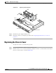
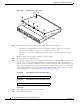
Replacing the Chassis Cover
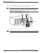
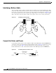
Step 8 Reconnect the AC power cord. Or, if you are using a DC-powered unit, refer to Figure B-18 or
Figure B-19, and complete Step a through Step e for each power supply.
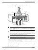
Warning
The illustration shows the DC power supply terminal block. Wire the DC power supply using the
appropriate lugs at the wiring end, or with no lugs, as illustrated. The proper wiring sequence is
ground to ground, positive to positive, and negative to negative. Note that the ground wire should
always be connected first and disconnected last.
Statement 197
Figure B-18 Connecting DC Power Supply—Single Power Supply
a.
Connect the DC connector to the rear of the power supply.
Caution Do not overtorque the terminal block contact screws. The recommended torque is 4.5 lb-in (0.50 N-m).
56022
Power switch
Source A - NEG
Source A - RTN
Source B - NEG
Source B - RTN
Ground
To DC source
DC connector