
Universal Gateway Chassis Installation Guide

B-10
Cisco AS5350XM Universal Gateway Chassis Installation Guide
OL-6417-02
Appendix B Replacing the Power Supply
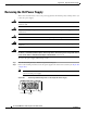
Installing the Power Supply
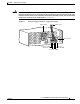
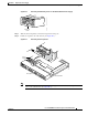
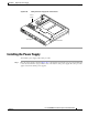
Figure B-11 Inserting the Power Supply in the Chassis
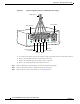
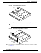
Step 2 Connect the two power connectors to the system board and backplane. (See Figure B-8.) Connect the
system board connector first, followed by the backplane connector. (See Figure B-12.)
Note The system board connector is located on the system board, below and to the left of the
backplane connector.
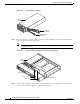
Figure B-12 Reconnecting the Power Cables to the Backplane
Step 3
Replace the air separator, holding all cables to the right of the separator as you slip it into the chassis.
(See Figure B-13.)
Power
supply
35695
3
Chassis bottom
Front panel
Power
supply
35696
3
Chassis bottom
Front panel
Power connector
Backplane