
Universal Gateway Chassis Installation Guide

B-2
Cisco AS5350XM Universal Gateway Chassis Installation Guide
OL-6417-02
Appendix B Replacing the Power Supply
Required Tools and Equipment
Warning
Before working on equipment that is connected to power lines, remove jewelry (including rings,
necklaces, and watches). Metal objects will heat up when connected to power and ground and can
cause serious burns or weld the metal object to the terminals.
Statement 43
Warning
Only trained and qualified personnel should be allowed to install or replace this equipment.
Statement 49
Warning
This product relies on the building’s installation for short-circuit (overcurrent) protection. Ensure that
a UL Listed and Certified fuse or circuit breaker no larger than 60 VDC, 15 A is used on all
current-carrying conductors.
Statement 96
Caution Before opening the chassis, ensure that you have discharged all static electricity from your body and that
the chassis is powered down.
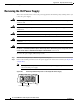
Required Tools and Equipment
You need the following tools and equipment:
• Medium-size Phillips screwdriver
• Small or medium flat-blade screwdriver
• ESD-preventive wrist strap
• Tie-wraps (optional)
• Antistatic bag (optional)
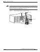
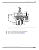
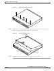
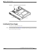
Removing the Chassis Cover
You must open the universal gateway chassis to gain access to its interior components.
To open the chassis cover, follow this procedure:
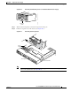
Step 1 Turn the power switch on the universal gateway off and disconnect site power.
Note Note that the power switch is part of the power supply.
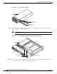
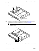
Step 2 If you are using a DC-powered unit, refer to Figure B-1 or Figure B-2 and complete the Step a through
Step d.
Warning
Before performing any of the following procedures, ensure that power is removed from the DC circuit.
Statement 1003