
Universal Gateway Chassis Installation Guide

A-7
Cisco AS5350XM Universal Gateway Chassis Installation Guide
OL-6417-02
Appendix A Replacing Memory Components
Replacing DIMMs
Warning
Before opening the unit, disconnect the telephone-network cables to avoid contact with
telephone-network voltages.
Statement 1041
Step 2 Remove all interface cables from the rear panel of the universal gateway.
Step 3 Attach an ESD-preventive wrist strap.
Step 4 Remove the chassis cover. (See the instructions in the “Removing the Chassis Cover” section on
page A-1.)
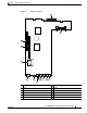
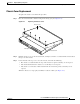
Step 5 Use Figure A-3 to locate the DIMM you are replacing.
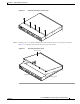
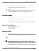
Step 6 Pull the socket latches away from the DIMM, and then pull the DIMM out of the socket. (See
Figure A-4.) The latches hold the DIMM tightly, so be careful not to break the socket.
Caution To prevent damage, do not press on the center of the DIMM. Handle the DIMM carefully.
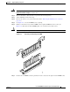
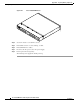
Figure A-4 Removing and Replacing the DIMM
Step 7
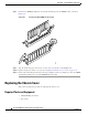
Position the new DIMM so that the polarization notch is located at the right end of the DIMM socket.
35685