
Universal Gateway Chassis Installation Guide

3-17
Cisco AS5350XM Universal Gateway Chassis Installation Guide
OL-6417-02
Chapter 3 Installing the Cisco AS5350XM Universal Gateway
Supplying Power
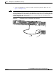
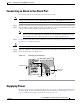
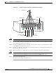
Figure 3-19 DC Power Supply Connections—Redundant Power Supply
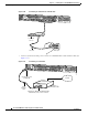
Caution Do not overtorque the terminal block contact screws. The recommended torque is 4.5 lb-in (0.50 N-m).
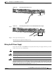
Step 3 Insert the safety ground (green wire) into the DC connector ground connector and tighten the locking
screws. Ensure that no bare wire is exposed.
Step 4 Insert the 48 VDC Return wires into the DC connector positive connectors (+) and tighten the locking
screws. Ensure that no bare wire is exposed.
Step 5 Insert the –48 VDC wires into the DC connector negative connectors (–) and tighten the locking screws.
Ensure that no bare wire is exposed.
Step 6 Make sure that the power supply wires are secured to cable strain-relief clamps with cable ties.
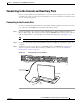
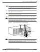
Warning
After wiring the DC power supply, remove the tape from the circuit breaker switch handle and
reinstate power by moving the handle of the circuit breaker to the ON position.
Statement 8
Step 7 Power up the universal gateway.
The internal power supply fan should power up.
A- A+
B- B+
82637
Power switch
Source A - NEG
Source A - RTN
Source B - NEG
Source B - RTN
Ground
To DC source
DC connector