
Universal Gateway Chassis Installation Guide

3-16
Cisco AS5350XM Universal Gateway Chassis Installation Guide
OL-6417-02
Chapter 3 Installing the Cisco AS5350XM Universal Gateway
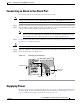
Supplying Power
Note This product is intended for installation in restricted access areas and is approved for connection using
12 or 14 AWG copper conductors only. The installation must comply with all applicable codes.
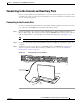
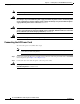
See Figure 3-18 or Figure 3-19 and follow these steps to wire the terminal blocks:
Step 1 Note the orientation of the DC power supply. The power supply cord should have three wires: 48 VDC
Return, –48 VDC, and a safety ground (green wire).
Note If you are installing a redundant power supply, you should attach appropriate-sized spade terminals to
the stripped ends of the ground and input wires.
Step 2 Strip off 1/4 in. (0.625 cm) of insulation on the safety ground, +48 VDC, and –48 VDC input wires.
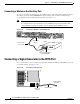
Warning
The illustration shows the DC power supply terminal block. Wire the DC power supply using the
appropriate lugs at the wiring end, or with no lugs, as illustrated. The proper wiring sequence is
ground to ground, positive to positive, and negative to negative. Note that the ground wire should
always be connected first and disconnected last.
Statement 197
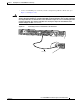
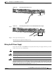
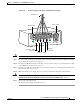
Figure 3-18 DC Power Supply Connections—Single Power Supply
Warning
The illustration shows the DC power supply terminal block. Wire the DC power supply using the
appropriate lugs at the wiring end, or with no lugs, as illustrated. The proper wiring sequence is
ground to ground, positive to positive, and negative to negative. Note that the ground wire should
always be connected first and disconnected last.
Statement 197
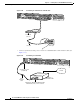
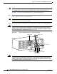
56022
Power switch
Source A - NEG
Source A - RTN
Source B - NEG
Source B - RTN
Ground
To DC source
DC connector