
Universal Gateway Chassis Installation Guide

3-14
Cisco AS5350XM Universal Gateway Chassis Installation Guide
OL-6417-02
Chapter 3 Installing the Cisco AS5350XM Universal Gateway
Supplying Power
Note The grounding architecture for the Cisco AS5350XM universal gateway is isolated DC return (DC-I).
Warning
Do not touch the power supply when the power cord is connected. For systems with a power switch,
line voltages are present within the power supply even when the power switch is off and the power
cord is connected. For systems without a power switch, line voltages are present within the power
supply when the power cord is connected.
Statement 4
Warning
This product relies on the building’s installation for short-circuit (overcurrent) protection. Ensure that
a fuse or circuit breaker no larger than 120 VAC, 15A U.S. (240 VAC, 10A international) is used on the
phase conductors (all current-carrying conductors).
Statement 13
Warning
The device is designed to work with TN power systems.
Statement 19
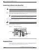
Connecting the AC Power Cord
To connect the power cord, follow these steps:
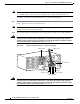
Note The redundant AC power supply has a non-standard connector. Use the electrical power cord that
came with your universal gateway.
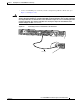
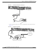
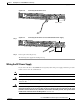
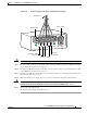
Step 1 Connect one end of the AC power cord to the power connector on the rear panel of the Cisco AS5350XM
universal gateway (See Figure 3-16 or Figure 3-17.)
Step 2 Connect the other end of the AC power cord to the power outlet.
Warning
The plug-socket combination must be accessible at all times, because it serves as the main
disconnecting device.
Statement 1019