
Getting Started Guide

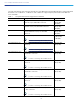


Table Of Contents
- Cisco Catalyst 9130AX Series Access Points
- 1 About this Guide
- 2 About the Cisco Catalyst 9130AX Series Wireless Access Point
- 3 Safety Instructions
- 4 Unpacking
- 5 AP Views, Ports, and Connectors
- 6 Preparing the AP for Installation
- 7 Installation Overview
- 8 Performing a Pre-Installation Configuration
- 9 Mounting the Access Point
- 10 Grounding the Access Point
- 11 Powering the Access Point
- 12 Configuring and Deploying the Access Point
- 13 Self-Identifying Antennas
- 14 Checking the Access Point LEDs
- 15 Miscellaneous Usage and Configuration Guidelines
- 16 FAQs
- 18 Declarations of Conformity and Regulatory Information
- 17 Related Documentation
- Manufacturers Federal Communication Commission Declaration of Conformity Statement
- VCCI Statement for Japan
- Guidelines for Operating Cisco Catalyst Access Points in Japan
- Statement 371—Power Cable and AC Adapter
- Industry Canada
- Canadian Compliance Statement
- European Community, Switzerland, Norway, Iceland, and Liechtenstein
- Declaration of Conformity for RF Exposure
- Generic Discussion on RF Exposure
- This Device Meets International Guidelines for Exposure to Radio Waves
- This Device Meets FCC Guidelines for Exposure to Radio Waves
- This Device Meets the Industry Canada Guidelines for Exposure to Radio Waves
- Cet appareil est conforme aux directives internationales en matière d'exposition aux fréquences radioélectriques
- Additional Information on RF Exposure
- Administrative Rules for Cisco Catalyst Access Points in Taiwan
- Operation of Cisco Catalyst Access Points in Brazil
- Declaration of Conformity Statements
- Communications, Services, and Additional Information
- Cisco Bug Search Tool

7
Cisco Catalyst 9130AX Series Access Points
Cisco also provides the following external antenna accessories:
2 ft Smart Antenna Connector to RP-TNC breakout cable (AIR-CAB002-D8-R=)—For conventional (non-DART)
antennas with gains up to 6 dBi
3 ft Smart Antenna Connector to N Connectors (AIR-CAB003-D8-N=)—For conventional (non-DART) antennas with
gains up to 13 dBi
Antenna bracket (AIR-AP-BRACKET-9=)—To mount the C9130AXE directly to the back of the C-ANT9103= antenna
3 Safety Instructions
Translated versions of the following safety warnings are provided in the translated safety warnings document that is
shipped with your access point. The translated warnings are also in the Translated Safety Warnings for Cisco Catalyst
Access Points, which is available on Cisco.com.
Warning
IMPORTANT SAFETY INSTRUCTIONS
This warning symbol means danger. You are in a situation that could cause bodily injury. Before you
work on any equipment, be aware of the hazards involved with electrical circuitry and be familiar with
standard practices for preventing accidents. Use the statement number provided at the end of each
warning to locate its translation in the translated safety warnings that accompanied this device.
SAVE THESE INSTRUCTIONS
Statement 1071
Warning
Read the installation instructions before using, installing or connecting the system to the power source.
Statement 1004
Warning
This product relies on the building’s installation for short-circuit (overcurrent) protection. Ensure that
the protective device is rated not greater than 20A.
Statement 1005
AIR-ANT2566P4W-R= Directional Antenna, 4-port, with RP-TNC
connectors.
Note Connect to AP using AIR-CAB002-D8-R=.
6 dBi (2.4 GHz)
6 dBi (5 GHz)
AIR-ANT2566P4W-RS= Directional Self-Identifying Antenna, 4-port, with
RP-TNC connectors.
Note Connect to AP using AIR-CAB002-D8-R=.
6 dBi (2.4 GHz)
6 dBi (5 GHz)
1. For the USA, the UNII-1 channels can be used only indoors.
Table 1 List of External Antennas Supported on C9130AXE
Part Number Description Gain