
Getting Started Guide

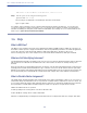


Table Of Contents
- Cisco Catalyst 9130AX Series Access Points
- 1 About this Guide
- 2 About the Cisco Catalyst 9130AX Series Wireless Access Point
- 3 Safety Instructions
- 4 Unpacking
- 5 AP Views, Ports, and Connectors
- 6 Preparing the AP for Installation
- 7 Installation Overview
- 8 Performing a Pre-Installation Configuration
- 9 Mounting the Access Point
- 10 Grounding the Access Point
- 11 Powering the Access Point
- 12 Configuring and Deploying the Access Point
- 13 Self-Identifying Antennas
- 14 Checking the Access Point LEDs
- 15 Miscellaneous Usage and Configuration Guidelines
- 16 FAQs
- 18 Declarations of Conformity and Regulatory Information
- 17 Related Documentation
- Manufacturers Federal Communication Commission Declaration of Conformity Statement
- VCCI Statement for Japan
- Guidelines for Operating Cisco Catalyst Access Points in Japan
- Statement 371—Power Cable and AC Adapter
- Industry Canada
- Canadian Compliance Statement
- European Community, Switzerland, Norway, Iceland, and Liechtenstein
- Declaration of Conformity for RF Exposure
- Generic Discussion on RF Exposure
- This Device Meets International Guidelines for Exposure to Radio Waves
- This Device Meets FCC Guidelines for Exposure to Radio Waves
- This Device Meets the Industry Canada Guidelines for Exposure to Radio Waves
- Cet appareil est conforme aux directives internationales en matière d'exposition aux fréquences radioélectriques
- Additional Information on RF Exposure
- Administrative Rules for Cisco Catalyst Access Points in Taiwan
- Operation of Cisco Catalyst Access Points in Brazil
- Declaration of Conformity Statements
- Communications, Services, and Additional Information
- Cisco Bug Search Tool

34
Cisco Catalyst 9130AX Series Access Points
What is a Smart Antenna connector?
The C9130AXE model has a Smart antenna connector (see Figure 17), which is connected directly to the flexible radio.
Without a supported external antenna connected to the Smart Antenna connector, the flexible radio can stay only in
2.4 GHz mode. If an external antenna is connected, the flexible radio can be used in the full Flexible Radio Assignment
mode.
To connect any supported RP-TNC connector-type external antenna to the Smart antenna connector, use the DART
cable connector AIR-CAB002-D8-R= (see Figure 18), which is to be procured separately from Cisco.
To connect any supported N connector-type external antenna to the Smart antenna connector, use the DART cable
connector AIR-CAB003-D8-N= (see Figure 19), which is to be procured separately from Cisco.
Figure 17 Smart Antenna Connector C9130AXE Model
Figure 18 AIR-CAB002-D8-R= DART Connector