
Integrated Services Router Installation Guide

8
Installing Memory and Power Over Ethernet in Cisco 880 Series Integrated Services Routers
OL-16194-01
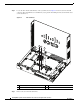
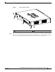
Opening the Chassis
Tip If the card is not installed in the correct direction, the three screw holes will not match up with the three
metal standoffs.
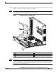
Step 5 Place the PoE card on top of the three metal standoffs, lining up the screw holes in the PoE card with the
metal standoffs.
Step 6 Push the PoE card down towards the system board until it is firmly fixed into the PoE connector.
Step 7 Insert the screws provided in the accessory kit through the PoE card and into the metal standoffs. See
Figure 5. Carefully tighten the screws with a Phillips screwdriver.
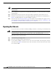
Step 8 Close the router (see Closing the Chassis, page 10), and then connect the PoE power supply to an AC
power outlet. To connect the PoE power supply to an AC power outlet, see the Cisco 860 and Cisco 880
Series Hardware Installation Guide, Connecting Power over Ethernet.
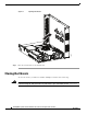
Opening the Chassis
To open the chassis, you will need a number-2 Phillips screwdriver, a wrist strap, and an antistatic mat.
Warning
During this procedure, wear grounding wrist straps to avoid ESD damage to the card. Do not directly
touch the backplane with your hand or any metal tool, or you could shock yourself.
Statement 94
Follow these steps to open the chassis:
Step 1 Disconnect the power supply cable.
Step 2 Disconnect all cables from the router back panel.
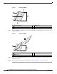
Step 3 Use the number-2 Phillips screwdriver to remove the screws at the middle on the back panel, and at the
sides of the router. Figure 6 shows the location of the screws. The screws are in the same location on all
Cisco 880 series ISRs.