
Network Router User Manual

4-29
Layer 3 Switching Software Feature and Configuration Guide
78-6235-04, Cisco IOS Release 12.0(10)W5(18)
Chapter 4 Configuring Interfaces
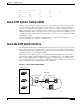
Configuring the ATM Uplink Interface (Catalyst 8540)
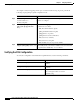
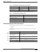
In addition, the ATM uplink interface uses the non-configurable values shown in Table 4-5.
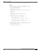
Initially Configuring the ATM Uplink Interface
You should configure the following properties for a newly installed ATM uplink interface:
• IP routing
• IP address
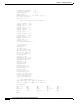
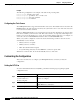
To initially configure the ATM uplink interface, perform the following steps, beginning in global
configuration mode:
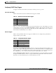
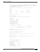
Transmit clock source [no] atm clock internal no internal (line)
Cisco Discovery Protocol (CDP) [no] cdp enable CDP enabled
ATM VCs per VP atm vc-per-vp 1024
Table 4-4 ATM Uplink Interface Default Configuration Values (continued)
Parameter Configuration Command Default Value
Table 4-5 ATM Uplink Interface Nonconfigurable Values
Parameter Value
Transmit buffers for segmentation and reassembly
(SAR)
8192
Receive buffers for SAR 8192
Maximum VCs 8192
ATM AAL AAL5
ILMI keepalives Not supported
Command Purpose
Step 1
Router(config)# ip routing Enables IP routing.
Step 2
Router(config)# interface atm
slot/subslot/interface
Router(config-if)#
Enters interface configuration mode and specifies the ATM
interface to configure.
Step 3
Router(config-if)# ip address
ip-address subnet-mask
Assigns an IP address and subnet mask to the interface.
Step 4
Router(config-if)# atm clock
internal
Specifies the internal clock for the interface. The default mode
for the clock is no internal, which is the same as the line clock.
Step 5
Router(config-if)# no shutdown Enables the interface with the previous configurations.