
Network Router User Manual

4-28
Layer 3 Switching Software Feature and Configuration Guide
78-6235-04, Cisco IOS Release 12.0(10)W5(18)
Chapter 4 Configuring Interfaces
Configuring the ATM Uplink Interface (Catalyst 8540)
Note The ATM uplink interface module does not work in a Catalyst 8540 MSR when the ATM
router module is present.
Configuring the ATM UplinkInterface (Catalyst 8540)
This section describes the default configuration of the ATM uplink interface, initial configurations you
should perform for a newly installed interface, and optional configurations you can do to customize the
interfaces to the requirements of your network.
Note The ATM uplink interface module consists of one OC-12c or OC-3c port and one
enhanced Gigabit Ethernet port. For instructions on configuring the enhanced Gigabit
Ethernet interface, see the “About the Enhanced Gigabit Ethernet Interfaces (Catalyst
8540)” section on page 4-5.
Configuration Overview
The following steps provide on overview of configuring an ATM uplink from the switch router to the
ATM network:
Step 1 Configure the ATM uplink interface:
a. Enable the ATM interface.
b. Customize the configuration by configuring PVCs and SVCs.
You must configure at least one PVC or SVC. The VC options you configure must match in three
places: on the switch router, on the ATM switch, and at the remote end of the PVC or SVC
connection.
Step 2 Configure the ATM switch to which the ATM uplink connects.
Default Configuration
On power up, the ATM uplink interface is shut down. When you enter the no shutdown command, the
interface is enabled with the default configuration values shown in Table 4-4.
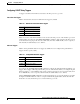
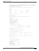
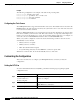
Table 4-4 ATM Uplink Interface Default Configuration Values
Parameter Configuration Command Default Value
Maximum transmission unit
(MTU)
[no] mtu bytes 4470 bytes
Loopback [no] loopback No loopback
SONET framing [no] atm sonet stm-1 for OC-3
[no] atm sonet stm-4 for OC-12
no stm-1
no stm-4