Cisco 805 Router Hardware Installation Guide Corporate Headquarters Cisco Systems, Inc. 170 West Tasman Drive San Jose, CA 95134-1706 USA http://www.cisco.
THE SPECIFICATIONS AND INFORMATION REGARDING THE PRODUCTS IN THIS MANUAL ARE SUBJECT TO CHANGE WITHOUT NOTICE. ALL STATEMENTS, INFORMATION, AND RECOMMENDATIONS IN THIS MANUAL ARE BELIEVED TO BE ACCURATE BUT ARE PRESENTED WITHOUT WARRANTY OF ANY KIND, EXPRESS OR IMPLIED. USERS MUST TAKE FULL RESPONSIBILITY FOR THEIR APPLICATION OF ANY PRODUCTS.
C ON T E N T S About This Guide Audience v v Organization v Conventions vi Terms and Acronyms viii Related Documentation Chapter 1 Product Overview Features Chapter 2 1-1 1-1 Front Panel 1-3 Back Panel 1-3 LEDs xi 1-5 Installing the Cisco 805 Router 2-1 Safety 2-1 Warnings 2-1 ESD 2-3 Required Equipment Unpacking the Box 2-4 2-5 Installing the Router 2-6 Connecting an Ethernet Device 2-6 Connecting a Hub 2-7 Connecting a Server, PC, or Workstation Connecting a Serial Device 2-10
Where to Go Next Chapter 3 Troubleshooting 2-17 3-1 Problems During First Startup 3-2 Problems After Router is Running 3-3 Before You Call Your Cisco Reseller Appendix A Selecting a Serial Cable 3-5 A-1 How to Select a Serial Cable A-1 DTE or DCE A-2 Signaling Standards A-4 Connector Gender A-4 Serial Connection Example A-5 Serial Cable Part Numbers A-6 Appendix B Technical Specifications B-1 Appendix C Connector and Cable Specifications Connector Specifications Cable Specifications Index
About This Guide This preface discusses the audience, organization, conventions, and terms and acronyms used in this guide. It also discusses related documentation and how to access electronic documentation. Audience This guide is intended for service technicians who have no experience installing routers. The goal of these technicians is to connect the router to the network as quickly as possible.
Conventions • Selecting a Serial Cable—Explains how to select a serial cable to connect your serial device to the router serial port. It also provides Cisco part numbers for cables that you can order. • Technical Specifications—Provides physical dimensions, environmental operating ranges, and power specifications for the router. • Connector and Cable Specifications—Contains port connector pinouts and specifications for cables that you might need to provide.
Conventions van de waarschuwingen die in deze publicatie verschijnen, kunt u het document Regulatory Compliance and Safety Information (Informatie over naleving van veiligheids- en andere voorschriften) raadplegen dat bij dit toestel is ingesloten. Varoitus Tämä varoitusmerkki merkitsee vaaraa. Olet tilanteessa, joka voi johtaa ruumiinvammaan. Ennen kuin työskentelet minkään laitteiston parissa, ota selvää sähkökytkentöihin liittyvistä vaaroista ja tavanomaisista onnettomuuksien ehkäisykeinoista.
Terms and Acronyms Aviso Este símbolo de aviso indica perigo. Encontra-se numa situação que lhe poderá causar danos físicos. Antes de começar a trabalhar com qualquer equipamento, familiarizese com os perigos relacionados com circuitos eléctricos, e com quaisquer práticas comuns que possam prevenir possíveis acidentes.
Terms and Acronyms crossover Ethernet cable A cable that wires a pin to its opposite pin; for example, Receive+ is wired to Transmit+. This cable connects two similar devices, such as a data terminal equipment (DTE) and data communications equipment (DCE) device. CSU/DSU Channel service unit/data service unit. Connect this type of device to router serial port for synchronous leased-line, Frame Relay, or X.25 connection. DCE Data communications equipment.
Terms and Acronyms equivalent hub button can affect the setting of this router button, refer to the “Connecting an Ethernet Device” section in Chapter 2, “Installing the Cisco 805 Router.” link Indicates that a connection between the router and an Ethernet device exists. MDI Media-dependent interface. A port on a Ethernet network device used to connect the device to the Ethernet network, usually through a hub or switch. MDI-X Media-dependent interface, crossover.
Related Documentation data, or other communication. These networks might be publicly or privately owned. They might be subjected to overvoltages due to atmospheric discharges or power line failures.
Related Documentation Documentation DVD Cisco documentation and additional literature are available in a Documentation DVD package, which may have shipped with your product. The Documentation DVD is updated regularly and may be more current than printed documentation. The Documentation DVD package is available as a single unit. Registered Cisco.com users (Cisco direct customers) can order a Cisco Documentation DVD (product number DOC-DOCDVD=) from the Ordering tool or Cisco Marketplace.
Related Documentation You can submit comments by using the response card (if present) behind the front cover of your document or by writing to the following address: Cisco Systems Attn: Customer Document Ordering 170 West Tasman Drive San Jose, CA 95134-9883 We appreciate your comments. Cisco Product Security Overview Cisco provides a free online Security Vulnerability Policy portal at this URL: http://www.cisco.com/en/US/products/products_security_vulnerability_policy.
Related Documentation Tip We encourage you to use Pretty Good Privacy (PGP) or a compatible product to encrypt any sensitive information that you send to Cisco. PSIRT can work from encrypted information that is compatible with PGP versions 2.x through 8.x. Never use a revoked or an expired encryption key. The correct public key to use in your correspondence with PSIRT is the one that has the most recent creation date in this public key server list: http://pgp.mit.
Related Documentation Note Use the Cisco Product Identification (CPI) tool to locate your product serial number before submitting a web or phone request for service. You can access the CPI tool from the Cisco Technical Support Website by clicking the Tools & Resources link under Documentation & Tools. Choose Cisco Product Identification Tool from the Alphabetical Index drop-down list, or click the Cisco Product Identification Tool link under Alerts & RMAs.
Related Documentation Definitions of Service Request Severity To ensure that all service requests are reported in a standard format, Cisco has established severity definitions. Severity 1 (S1)—Your network is “down,” or there is a critical impact to your business operations. You and Cisco will commit all necessary resources around the clock to resolve the situation.
Related Documentation troubleshooting tips, configuration examples, customer case studies, certification and training information, and links to scores of in-depth online resources. You can access Packet magazine at this URL: http://www.cisco.com/packet • iQ Magazine is the quarterly publication from Cisco Systems designed to help growing companies learn how they can use technology to increase revenue, streamline their business, and expand services.
Related Documentation xviii Cisco 805 Router Hardware Installation Guide
CHAPTER 1 Product Overview The Cisco 805 router can connect a remote office to a corporate office or a small professional office to an Internet service provider (ISP). In the remote-office-to-corporate-office network, the remote office is typically a small professional office that is part of a larger corporation, such as a real estate office. Although a majority of its data might exist at the remote office itself, the remote office might also need to exchange data with its larger corporate office.
Features Table 1-1 Feature Description Flash memory Router provides 4 MB of Flash memory.1 Dynamic RAM (DRAM) Router provides 8 MB of DRAM.1 Ease of installation Color-coded ports and cables reduce the chance of error. Cisco IOS software Router supports a subset of Cisco IOS software. Cisco 805 Fast Step software Provides a Windows 95, Windows 98, and Windows NT software tool for basic Cisco 805 configuration. Cable lock Provides a way to physically secure router.
Front Panel Front Panel Figure 1-1 describes the Cisco 805 front panel. Figure 1-1 Cisco 805 Front Panel WAN LEDs Indicate packets are sent to or received from serial port. 17281 LAN LEDs Indicate packets are sent to or OK LED received from Indicates Ethernet port. router has power. For more details, see the “LEDs” section later in this chapter. Back Panel Figure 1-2 describes the Cisco 805 back panel.
Back Panel Figure 1-2 Cisco 805 Back Panel LINK LED Indicates state of Ethernet port. On when connected. Ethernet port Connects Ethernet network device. HUB NO HU B ETHERN ET CONSOL 10 BASE Cable lock Physically secures router. E T Power switch l = On = Standby or no power output Cisco 80 5 SERIAL Console port Connects PC or terminal. HUB/NO HUB button (for Ethernet port) Identifies device connected to Ethernet port and determines Ethernet cable.
LEDs LEDs Table 1-2 summarizes the function of each LED. All LEDs are on the router front panel except for the LINK LED, which is on the router back panel. Table 1-2 LED Functions LED Corresponding Port/Component Color Function OK Power Green On when power is supplied to the router and when the router completes the self-test procedure and begins operating. LAN Ethernet Green On when the Ethernet interface is up. Off when the Ethernet interface has been shut down.
LEDs 1-6 Cisco 805 Router Hardware Installation Guide
CHAPTER 2 Installing the Cisco 805 Router This chapter provides information on the following topics: • • • • • Safety Required Equipment Unpacking the Box Installing the Router Where to Go Next Safety This section contains information on warnings associated with using your router and on electrostatic discharge (ESD). Warnings Before installing the router, read the following warnings: Warning Only trained and qualified personnel should be allowed to install or replace this equipment.
Safety Warning Before working on a system that has a standby/on switch, turn the power to standby and unplug the power cord. Warning Before working on equipment that is connected to power lines, remove jewelry (including rings, necklaces, and watches). Metal objects will heat up when connected to power and ground and can cause serious burns or weld the metal object to the terminals. Warning Ultimate disposal of this product should be handled according to all national laws and regulations.
ESD Figure 2-1 SELV Circuit Ports Includes SELV circuits LINK HUB NO HU B ETHERN ET CONSOL T Cisco 80 5 SERIAL 24848 10 BASE E ESD ESD is a transfer of electrostatic charge between bodies of different electrostatic potentials, such as an operator and a piece of electrical equipment. It occurs when electronic components are improperly handled, and it can damage equipment and impair electrical circuitry.
Required Equipment Caution Periodically check the resistance value of the antistatic strap, which should be between 1 and 10 megohms (Mohms). Required Equipment You need to provide the following equipment: 2-4 • The hub, server, workstation, or PC that you plan to connect to the Ethernet port. The server, workstation, or PC must have a 10- or 10/100-Mbps network interface card (NIC).
Unpacking the Box Unpacking the Box The items that come with your router are listed below. All these items are in the accessory kit that is inside the box that your router came in. If any of the items is missing or damaged, contact your customer service representative.
Installing the Router Installing the Router To install the router, perform the following tasks in the following order: 1 Connect an Ethernet device. 2 Connect a serial device. 3 Connect a terminal or PC (for software configuration or router troubleshooting). 4 Connect the power supply. 5 Mount the router. 6 Verify the router installation.
Connecting an Ethernet Device Table 2-1 Connecting Ethernet Devices Router HUB/NO HUB Button Setting Hub Button Setting1 Hub with equivalent to router HUB/NO HUB button HUB (in) MDI (in) Hub with equivalent to router HUB/NO HUB button NO HUB (out) MDI-X (out) Hub without equivalent to router HUB/NO HUB button NO HUB (out) MDI-X (out) Server, PC, or workstation NO HUB (out) – Network Device Connected to Router 1 Hub vendors choose different names for the button controlling cable selection.
Installing the Router Figure 2-2 Connecting a Hub Cisco 805 router 1. Set HUB/NO HUB button. HUB LINK NO HUB ETHERN ET CONSOL E 10 BASE Cisco 80 5 T SERIAL 2. Connect yellow cable to yellow Ethernet port. Cisco 1528 Micro Hub 10/100 1X SPEED LED 100Bas eTX SO 10Base LID T BLI NK 2X ETH ERN ET 3X 4X 1 2 3 4 5 6 7 8 6X 7X 8X 3. Connect other end of cable to hub. MDI-X 4. If applicable, check setting of hub equivalent of router HUB/NO HUB button.
Connecting an Ethernet Device Figure 2-3 Connecting a Server, PC, or Workstation Cisco 805 router 1. Set HUB/NO HUB button. HUB LINK NO HUB ETHERN ET CONSOL E 10 BASE T Cisco 80 5 SERIAL 2. Connect yellow cable to yellow Ethernet port. 17285 OK SER 0 AUX LAN ETH PC 3. Connect other end of cable to server, PC, or workstation.
Installing the Router Connecting a Serial Device You can connect any one of several serial devices to the router serial port. For more information, see the “DTE or DCE” section in Appendix A, “Selecting a Serial Cable.” Table 2-2 describes the devices most commonly connected to the router serial port and how these devices are used.
Connecting a Serial Device Figure 2-4 Connecting a Modem or CSU/DSU Cisco 805 router HUB NO HUB ETHERN ET CONSOL E 10 BASE T Cisco 80 5 SERIAL 1. Connect appropriate end of serial cable to dark blue serial port. Modem or CSU/DSU 2. Connect other end of cable to modem or CSU/DSU.
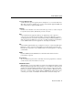
Installing the Router Connecting a Terminal or PC You can connect either a terminal or PC from which you can configure the software or troubleshoot problems with the router. Follow the steps in Figure 2-6. Figure 2-5 Connecting Terminal or PC Cisco 805 router HUB LINK NO HUB ETHERN ET CONSOL E 10 BASE T3 Cisco 80 5 SERIAL 1. Connect light blue cable to light blue Console port. 3. Connect DB-9 or DB-25 connector to terminal or PC. 2.
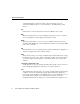
Connecting the Power Supply Connecting the Power Supply Follow the steps in Figure 2-7 to connect the power supply. Warning The device is designed to work with TN power systems. Warning This product relies on the building’s installation for short-circuit (overcurrent) protection. Ensure that a fuse or circuit breaker no larger than 120 VAC, 15A U.S. (240 VAC, 16A international) is used on the phase conductors (all current-carrying conductors). Warning This equipment is intended to be grounded.
Installing the Router Mounting the Router You can mount the router on one of the following surfaces: • • Table or other horizontal surface Wall or other vertical surface Mounting the Router on a Table You can mount your router on a table or other horizontal surface. Use the following guidelines: • • Do not cover or obstruct the router vents, which are located on the router sides. You can stack a maximum of five routers on top of one another.
Mounting the Router Figure 2-7 Wall-Mounting Brackets (Bottom of Router) Front panel of router Mounting bracket Mounting bracket 7 58 in. (19.35 cm) 11671 Bottom of router When mounting the router, the following conditions must be met: • Because you will use the front panel LEDs as status and problem indicators, the router front panel must face upward and be easily visible. • • The back panel must face downward to reduce strain on the cable connections.
Installing the Router Figure 2-8 Mounting the Router on a Wall 5 1. Secure two screws 7 8 in. (19.35 cm) apart in a wall and 18 in. (0.32 cm) from the wall. 2. Hang router on screws. ) m 5c Wall 7 5 8 in. Wall-mount screw 9.3 Front panel (1 Mounting brackets Wall-mount screw 1 8 in. (0.32 cm) Wall Screw 3. Place power supply on horizontal surface.
Verifying Installation Verifying Installation Verify the power, Ethernet, and serial connections by checking the LEDs. Table 2-3 describes the normal pattern for each LED and what to do if you get an abnormal pattern. Table 2-3 Verifying Installation LED Normal Pattern OK Explanation If Abnormal Pattern On Power is supplied to the router. Router completes self-test procedure and begins operating. If off, refer to Chapter 3, “Troubleshooting.” LINK On (LINK LED is located on router back panel.
Where to Go Next 2-18 Cisco 805 Router Hardware Installation Guide
CHAPTER 3 Troubleshooting This chapter describes problems that could occur with the Cisco 805 router hardware, reasons for the problems, and steps to solve the problems. The problems are grouped into the following states: • • • During first startup After first startup After router has been up and running For more information on problems that could occur with the software, refer to the Cisco 805 Router Software Configuration Guide.
Problems During First Startup Problems During First Startup Table 3-1 lists problems that could occur the first time you turn on the power switch. Table 3-1 Problems During First Startup Symptom Problem All LEDs, including OK LED, are off. No power to router. Solutions Perform the following tasks in the following order: 1 Make sure that the power switch is set to ON. 2 Make sure that all connections to and from the power supply are secure. 3 Make sure that the power outlet has power.
Problems After Router is Running Table 3-1 Symptom Problems During First Startup (continued) Problem Solutions • Improperly connected cable. • To make sure that you have cabled properly, refer to Figure 2-5 in Chapter 2, “Installing the Cisco 805 Router.” • Make sure the connectors at both ends of the cable are securely seated. • Improperly functioning modem or channel service unit/data service unit (CSU/DSU). • Refer to the documentation that accompanies your modem or CSU/DSU.
Problems After Router is Running Table 3-2 Problems After Router is Running (continued) Symptom Problem Solutions • Improperly functioning NIC on server, PC, or workstation. • Run the NIC diagnostic supplied by the vendor to make sure it is functioning properly. If it is not, replace it. • If the problem continues after these checks, call your Cisco reseller. Connection to the serial device is intermittent or lost. (The CD LED on the front panel is off.
Before You Call Your Cisco Reseller Before You Call Your Cisco Reseller Some of the solutions in this chapter instruct you to contact your Cisco reseller.
Before You Call Your Cisco Reseller 3-6 Cisco 805 Router Hardware Installation Guide
APPENDIX A Selecting a Serial Cable This appendix provides the following information: • • How to select a serial cable to connect your serial device Cisco part numbers for serial cables that you can order How to Select a Serial Cable To select a serial cable, you must answer the following questions about the serial device that you plan to connect to the router serial port: • Is this device a data terminal equipment (DTE) or data communications equipment (DCE) device? • • What signaling standard doe
How to Select a Serial Cable DTE or DCE There are two types of devices that can communicate over a serial interface: DCE and DTE. A DCE provides a physical connection to a network and forwards traffic. A DTE connects to a network through a DCE device. Typically, a DTE device is connected to a DCE device (or vice versa) rather than another DTE device. Check the documentation that ships with your serial device to determine if it is a DTE or DCE device.
DTE or DCE Table A-2 Cable Type Needed to Connect Serial Devices Serial Device Type Cable Type Needed DCE DTE Selecting a Serial Cable A-3
How to Select a Serial Cable Signaling Standards Several standards define the signaling over the serial connectors on the router and serial device, the serial cable, and the cable connectors. You can connect a serial device with the following types of connectors to the router serial port: • • • • • • EIA/TIA-232 EIA/TIA-449 EIA/TIA-530 EIA/TIA-530A X.21 V.35 Check the documentation that ships with your serial device to determine the type of serial connector on your serial device.
Serial Connection Example Serial Connection Example Figure A-1 shows a typical serial connection for the Cisco 805 router. In this example, the router, which is a DTE device, is connected to a CSU/DSU or modem, which are DCE devices. Figure A-1 Serial Connection Example Cisco 805 router CSU/DSU or modem DTE device DCE device (provides clocking) 18958 V.35 DTE cable The CSU/DSU or modem and its serial connector have the following characteristics: • • • DCE device V.
Serial Cable Part Numbers Serial Cable Part Numbers Table A-3 summarizes serial cables that you can order from Cisco.
APPENDIX B Technical Specifications Table B-1 outlines the technical specifications for the Cisco 805 router. Table B-1 Technical Specifications Description Design Specification Physical Dimensions Dimensions (H x W x D) 2.0 x 9.7 x 8.3 in. (5.1 x 24.6 x 21.1 cm) Weight (does not include desktop power supply) 1.5 lbs (0.
For information on regulatory compliance, refer to the Regulatory Compliance and Safety Information for the Cisco 805 Router document that shipped with your router. Warning Ultimate disposal of this product should be handled according to all national laws and regulations.
APPENDIX C Connector and Cable Specifications This appendix provides connector and cable specifications for the Cisco 805 router. Connector Specifications This section provides pinouts for the following connectors: • • • • Ethernet—Table C-1 Console—Table C-2 Serial (basic)—Table C-3 Power—Table C-4 Function 1 in Table C-1 describes how the connector functions when the HUB/NO HUB button is in the HUB (in) position.
Connector Specifications Table C-1 Pin Function 1 Function 2 7 Unused Unused 8 Unused Unused Table C-2 C-2 Ethernet Connector Pinouts (RJ-45) (continued) Console Connector Pinouts (RJ-45) Pin Function 1 Request to send 2 Data terminal ready 3 Transmit 4 Ground 5 Ground 6 Receive 7 Data set ready 8 Clear to send Cisco 805 Router Hardware Installation Guide
Connector Specifications Table C-3 Serial Connector Pinouts (SCSI) Pin Function Pin Function 1 O_Transmit/receive+ 14 O_Transmit/receive- 2 O_Transmit clock echo/receive clock+ 15 O_Transmit clock echo/receive clock- 3 B_Transmit clock/transmit clock+ 16 B_Transmit clock/transmit clock- 4 I_Receive clock/transmit clock echo+ 17 I_Receive clock/transmit clock echo- 5 I_Receive/transmit+ 18 I_Receive/transmit- 6 B_Data carrier detect/data carrier detect+ 19 B_Data carrier detect/
Cable Specifications Cable Specifications Table C-5 provides Ethernet cable specifications. Table C-5 Ethernet Cable Specifications Type Category Shielding 10BaseT 3, 4, or 5 Unshielded twisted-pair (UTP) The maximum distance for the Ethernet cable is 328 ft (100 m).
INDEX A accessory kit 2-5 adapter, included 2-5 altitude specifications B-1 B brackets illustrated 2-15 C cable lock illustrated 1-4 cables Ethernet 1-4 included with router 2-5 not included with router 2-5 pinouts C-1 serial 2-10 ordering A-6 selecting A-1 cabling pinouts C-1 specifications C-4 caution statements, defined vi CD LED 1-3, 1-5, 2-17 CD RXD LED 1-3, 1-5 CD TXD LED 1-3, 1-5 Cisco 805 Fast Step software 2-17 Cisco reseller, contacting 3-5 configuring software 2-17 connecting Ethernet devices
hub, connecting 2-7 HUB/NO HUB button illustrated 1-4 settings 1-4, 2-6 humidity specifications B-1 I power connector illustrated 1-4 power problems 3-2 power specifications B-1 power supply connecting 2-13 power switch illustrated 1-4 R installation, verifying 2-17 installing the router 2-6 router unpacking 2-5, ?? to 2-5 router damage, preventing 2-3 L LAN LED 1-3, 1-5 LAN RXD LED 1-3, 1-5 LAN TXD LED 1-3, 1-5 LINK LED 1-5, 2-17 M mounting router 2-14 O S safety warnings 2-1 selecting serial ca
U unpacking the router 2-5, ?? to 2-5 V voltage specifications B-1 W wall brackets illustrated 2-15 wall mounting 2-14, 2-16 warning statements, defined vi warnings, installation 2-1 workstation, connecting 2-8 Index 3
Index 4 Cisco 805 Router Hardware Installation Guide