
Network Router User's Manual


Configuring SVCs, PVCs, SoftPVCs, PVPs, and VPTunnels 3-21
Configuring VP Tunnels
Configuring VP Tunnels
A VP tunnel is a method of linking two private ATM networks across a public network that
does not support SVCs. The VP tunnel provides a permanent path through the public
network. The public network transparently trunks the entire collection of virtual channels
in the virtual path between the two private networks. Signaling traffic is mapped into the
PVP and the switches allocate a virtual channel connection (VCC) on that VP, instead of
the default VP 0. This mapping allows the signaling traffic to pass transparently through
the public network.
Figure3-5 illustrates how to set up VP tunnels. This example network is used throughout
this section.
Figure3-5 Example Network for Configuring VP Tunnels
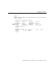
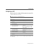
Table3-4 describes the interfaces and associated VPIs and VPTs for the VP tunnel shown
in Figure3-5. Between the source and destination ATM switch routers, the VPIs and VPTs
must match. For example, in Figure3-5, the VPIs and VPTs (99) match between ATM
switch routers A and B.
Table3-4 VPIs and VPTs for the Example VP Tunnel
Switch A Switch B
Interface
3/0/2.99 0/0/0.99
VPI
99 99
VPT
99 99