
Network Router User's Manual

Configuring SVCs, PVCs, SoftPVCs, PVPs, and VPTunnels 3-19
Configuring PVPs
Configuring PVPs
A VP connection is like a bundle of VCs, transporting all cells with a common VPI, rather
than a specific VPI and VCI. A PVP is a provisioned VP (like a PVC).
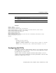
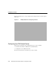
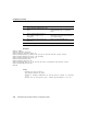
Figure3-4 illustrates how to set up PVPs. This example network is used throughout this
section.
Figure3-4 Example Network for Configuring PVPs
Table3-3 describes the in and out interfaces and associated VPIs for the PVP shown in
Figure3-4. Between ATM switch routers, the VPIs for the out port and the in port must
match. For example, in Figure3-4, the VPIs match between ATM switch routers A and B
(VPI=3).
Note The VPIs for the internal crossconnects do not have to match. For example, in
Figure3-4, the VPIs do not match in ATM switch router A for the internal crossconnect
between ports 3/0/1 (VPI=2) and 3/0/2 (VPI=3).
Table3-3 VPIs for the Example PVP
Switch A Switch B Switch B Switch C Switch C Switch D
Out In Out In Out In
Interface
3/0/2 0/0/0 1/1/1 3/1/1 1/0/0 0/1/1
VPI
3 3 5 5 8 8