
Network Router User's Manual

Configuring SVCs, PVCs, SoftPVCs, PVPs, and VPTunnels 3-15
Configuring the ATM Switch Router
Determining the Destination ATM Switch Router NSAP Address
Determine the destination ATM switch router NSAP address for the interface. See the
ATM switch router C in Figure3-3.
Take these steps:
Example
Switch# show atm address
Switch Address(es):
47.00918100000000E04FACB401.00E04FACB401.00 active
Soft VC Address(es):
47.0091.8100.0000.00e0.4fac.b401.4000.0c84.9030.00 ATM-P9/1/3
47.0091.8100.0000.0061.E5B5.C011.1111.1122.2222.00 ATM0/0/1
47.0091.8100.0000.00e0.4fac.b401.4000.0c85.0020.00 ATM0/1/0
47.0091.8100.0000.00e0.4fac.b401.4000.0c85.0030.00 ATM0/1/1
ILMI Switch Prefix(es):
47.0091.8100.0000.00e0.4fac.b401
ILMI Configured Interface Prefix(es):
LECS Address(es):
47.0091.8100.0000.00e0.4fac.b401.00e0.4fac.b405.00
Switch#
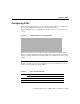
Step Command Purpose
1 Switch# show atm addresses
On the destination ATM switch router,
display the destination ATM address. You
need this address to complete the soft PVC.
Write the address in the space provided
below (or copy it to memory):
2 (No command.)
Proceed to the next section, “Configuring
the Source ATM Switch Router” to
complete the soft PVC.