C H A P T E R 3 Building the Network After you have planned your network, you can begin building the network components: groups, network partitions, subnetworks, NEs, links, and network maps. This chapter contains the following sections: • 3.1 Overview, page 3-1 • 3.2 How Do I Build Groups?, page 3-2 • 3.3 How Do I Build Network Partitions?, page 3-4 • 3.4 How Do I Build Subnetworks?, page 3-6 • 3.5 How Do I Build NEs?, page 3-7 • 3.6 How Do I Build Links?, page 3-28 • 3.
Chapter 3 Building the Network 3.2 How Do I Build Groups? • Links—Physical or logical entities (for example, a fiber) between two physical points (for example, ports). Circuits are provisioned through links. • Network Maps—Geographic representation of the NEs in the domain, the circuits and links between NEs, and the number of alarms associated with NEs. 3.2 How Do I Build Groups? NEs in the Domain Explorer are organized into groups, which consist of NEs and/or other groups.
Chapter 3 Building the Network 3.2.3 Moving Groups Note Tip A group cannot be pasted into the Discovered NEs or Deleted NEs group. The drag-and-drop feature can also be used to copy groups. Hold down the Ctrl key and use the mouse to drag and drop the group to a new location. Since they cannot see the entire domain, users with the Assign NEs property (Provisioner, Operator, and some custom user profiles) are not allowed to modify the topology using copy, cut, paste, or drag and drop.
Chapter 3 Building the Network 3.3 How Do I Build Network Partitions? 3.2.4.2 Deleting Multiple Groups Step 1 In the Domain Explorer tree, select the group to be deleted. Select multiple groups by pressing the Ctrl key, then click each group that will be deleted. Step 2 You can delete either the selected instance of the groups or all instances of the groups: • To remove the selected instance of the groups, choose Edit > Delete; then, click Yes in the confirmation dialog box.
Chapter 3 Building the Network 3.3.2 Modifying Network Partitions Table 3-2 Step 4 Field Descriptions for the Add New Network Partition Dialog Box Field Description Network Partition ID ID of the network partition. The ID must contain a minimum of 1 and a maximum of 128 alphanumeric or special characters. Description Network partition description. Click OK. The new network partition appears in the Subnetwork Explorer tree. 3.3.
Chapter 3 Building the Network 3.4 How Do I Build Subnetworks? Step 3 In the confirmation dialog box, click Yes. The network partition is removed from the Subnetwork Explorer tree. 3.4 How Do I Build Subnetworks? Subnetworks are sets of NEs interconnected at a specific network layer (such as physical, section, line, and so on). Subnetworks are contained within network partitions. NEs must belong to the same subnetwork in order to create circuits between them.
Chapter 3 Building the Network 3.4.2 Moving Subnetworks Note The Add New Subnetwork feature is not available for users with the Assign NEs property (Provisioner, Operator, and custom user profiles) because they cannot see the entire domain. 3.4.2 Moving Subnetworks A subnetwork can be moved from one network partition to another if there are no routable links among the NEs that belong to that subnetwork and if automatic subnetwork grouping is disabled.
Chapter 3 Building the Network 3.5.1 Prerequisites for Adding NEs 3.5.1 Prerequisites for Adding NEs Before adding a new NE, you must enable the NE service for that NE. The NE service is enabled by default, but the service is not started as a process unless you activate an NE for that particular service. You must also meet certain other specific prerequisites depending on the type of NE you are adding.
Chapter 3 Building the Network 3.5.1 Prerequisites for Adding NEs Note To add an ONS 15302 or ONS 15305 NE to CTM, its SNMP Users table must contain the following row: 0.0.0.0 public true where, public is the community string. In addition, to obtain the trap events from the NE, the CTM Server IP address must be added to the NE. Refer to the Cisco Edge Craft User Documentation for more information. 3.5.1.
Chapter 3 Building the Network 3.5.1 Prerequisites for Adding NEs – Trap port: 162 – Version: v1 – Community string: Same as on the GNE Note 2. If there is a direct connection from the ENE to GNE, it becomes the Relay A NE. If there are intermediate NEs between the ENE and GNE, these NEs must be specified as the relays. The community strings should be the same on all the NEs, including the relay NEs.
Chapter 3 Building the Network 3.5.1 Prerequisites for Adding NEs To add entries to the SNMP Community String table: Step 1 In the Domain Explorer window, choose Administration > ONS 155XX > ONS 155XX SNMP Settings Table. The SNMP Community String table opens. Table 3-5 provides descriptions. Step 2 If the IP address of the NE is not already in the table, choose Edit > Add. The Add SNMP Parameters dialog box opens.
Chapter 3 Building the Network 3.5.1 Prerequisites for Adding NEs 3.5.1.4.3 Topology Setup Appropriate topology information must be configured on ONS 15501, ONS 15530, and ONS 15540 NEs for automatic discovery of neighbors and discovery of physical links. For the ONS 15530 and ONS 15540, topology can be configured in two ways: by using CDP learning or through IP using Ethernet. For the ONS 15501, topology must be configured manually.
Chapter 3 Building the Network 3.5.1 Prerequisites for Adding NEs For NEs with OSC, additional configuration is required. Add patches between the Wave and OSC filter interfaces. For example, if the Wave 0 interface is connected physically to the OSC filter 0/0 interface, add a patch using the following command: patch Wave 0 Oscfilter 0/0 3.5.1.4.5 Unbundled CiscoView (Optional) In CTM, CiscoView is used for configuring and monitoring ONS 155xx NEs.
Chapter 3 Building the Network 3.5.1 Prerequisites for Adding NEs • Create a username and password with appropriate privileges. • After configuring the NE, add a seed NE to CTM. CTM automatically discovers the interconnected CRS-1 or XR 12000 NEs. Note Note The CRS-1 and XR 12000 discovery does not put the NE in service automatically. The discovery process adds the discovered NEs to CTM; however, you must mark the NEs as In Service. • Enable CDP on the NE for network discovery.
Chapter 3 Building the Network 3.5.1 Prerequisites for Adding NEs To configure the SNMP community string, you must change the community strings on the devices through the CLI. Table 3-6 describes the various options involved in configuring SNMP. Table 3-6 SNMP Configuration Options Option Description Domain Explorer, Network Element Properties pane, NE Authentication tab After saving the community strings information, the CTM processes use the new community strings for SNMP accesses.
Chapter 3 Building the Network 3.5.1 Prerequisites for Adding NEs where ro is the SNMP get community string and rw is the SNMP set only community string. Step 3 Enter the following command to configure the SNMP get community string: xxyyzz% cnfsnmp community public ro xxyyzz% Step 4 Enter the following command to check that the community string has changed: dspsnmp You will see output similar to the following example: xxyyzz.7.PXM.a > dspsnmp xxyyzz System Rev: 05.00 Dec.
Chapter 3 Building the Network 3.5.2 Adding NEs Step 1 Open a terminal window and SSH or Telnet to the switch. Step 2 Enter the cnfpasswd command to change the service-level password for all nodes. The following example is shown: xxyyzz.7.PXM.a > xxyyzz.7.PXM.a > cnfpasswd Enter existing password: Enter new password: Re-enter new password: Local password for user cisco changed. Step 3 When you are prompted for a password, you must: a. Enter the existing password. b. Enter the new password. c.
Chapter 3 Building the Network 3.5.2 Adding NEs If you click Finish in this window, Cisco default values will be assigned to the remaining fields. Note Step 4 Note Enter the following information. Fields shown depend on the NE type. a. NE ID • Do not use “CTM” as an NE ID because the Alarm Browser might contain CTM alarms with the source ID “CTM.” It will be difficult to distinguish between NE alarms and CTM alarms if they both have the same source ID (“CTM”).
Chapter 3 Building the Network 3.5.2 Adding NEs Step 10 Verify that the NE software version is listed in the Supported NE table (Domain Explorer > Administration > Supported NE Table). If it is not listed, see 4.3.7 Adding a New NE Software Version to the CTM Domain, page 4-37. 3.5.2.2 Adding Multiple NEs Note Step 1 Table 3-7 describes the fields in the Add New NE wizard.
Chapter 3 Building the Network 3.5.2 Adding NEs h. Location name i. Subnetwork ID j. Network Partition ID Make sure to specify the correct partition. If the wrong partition is specified, the new NE is not added and an error message appears. Caution Step 5 Click Next if you are adding an ONS 15302, ONS 15305, ONS 15327, ONS 15454 SONET, ONS 15454 SDH, ONS 15501, ONS 15530, ONS 15540, or ONS 15600 SONET NE.
Chapter 3 Building the Network 3.5.2 Adding NEs Table 3-7 Field Descriptions for the Add New NE Wizard (continued) Field Description IP Address (for single NE additions) Enter a unique IP address for the NE. It must be in the form ddd.ddd.ddd.ddd, where ddd is a decimal octet expressed as an integer between 0 and 255. The first octet cannot be a zero. From IP Address (for bulk NE additions) Note Prior to the NE ID discovery, CTM uses the NE IP address as a temporary NE ID.
Chapter 3 Building the Network 3.5.2 Adding NEs Table 3-7 Field Descriptions for the Add New NE Wizard (continued) Field Description NE Service Level Password Enter the password to use for CTM server-to-NE connections. Description Enter a description of the NE. Location Name Enter the NE geographic location. Subnetwork ID (not selectable if automatic subnetwork grouping is enabled) Select the subnetwork ID associated with the NE.
Chapter 3 Building the Network 3.5.3 Copying an NE from One Group to Another 3.5.3 Copying an NE from One Group to Another Groups for multiple users can easily be created in CTM. Just copy the same NE into different groups. Step 1 In the Domain Explorer tree, select the NE to be copied. Step 2 Choose Edit > Copy (or click the Copy tool). Step 3 Select the group or management domain node where the NE will be pasted and choose Edit > Paste (or click the Paste tool).
Chapter 3 Building the Network 3.5.5 Moving an NE from One Network Partition to Another 3.5.5 Moving an NE from One Network Partition to Another Caution Note CTM cannot manage circuits across network partitions. Make sure that all connected NEs are managed under the same network partition. Do not add SONET and SDH NEs in the same network partition. Step 1 In the Domain Explorer tree, select File > Subnetwork Explorer. The Subnetwork Explorer opens.
Chapter 3 Building the Network 3.5.7 Deleting NEs Step 3 Note Click Save. If a topological link is deleted while NEs are automatically grouped in subnetworks, CTM deletes isolated NEs, creates a new subnetwork, and moves the deleted NEs to the new subnetwork. If a topological link is discovered or added manually, it will result in a network that contains disjointed subnetworks.
Chapter 3 Building the Network 3.5.7 Deleting NEs Note If a CTC-based NE is deleted and then DCC connectivity to the deleted NE is removed, CTM rediscovers the deleted NE. If DCC connectivity is removed before deleting the NE, CTM does not rediscover the NE. Therefore, remove DCC connectivity to the NE before deleting the NE from CTM. 3.5.7.2 Deleting Multiple NEs Step 1 For each NE that will be deleted: a. In the Domain Explorer tree, select the NE that will be deleted. b.
Chapter 3 Building the Network 3.5.7 Deleting NEs Aside from using the Domain Explorer to remove an out-of-service NE from the database, you can also use the prune_ne.sh script. Note Shut down the CTM server and all CTM clients before running the prune_ne.sh script. Step 1 In the Domain Explorer tree, select the NE that will be removed. Step 2 In the Status tab of the Network Element Properties pane, set the Operational State field to Out of Service; then, click Save. Step 3 Close the CTM client.
Chapter 3 Building the Network 3.5.8 Restoring a Deleted NE Note • Wait until all records associated with the NE are deleted from the database before adding the NE back again. • The amount of time it takes to prune NEs depends on the amount of data that needs to be removed, the amount of data in the database, the system performance, and so on. The Deleted Network Elements group is seen by users who have add_delete_NE_group operation permission.
Chapter 3 Building the Network 3.6.1 Setting Up ONS 15501, ONS 15530, and ONS 15540 NEs for Link Discovery Note An autodiscovered link between two TPs will override previously autodiscovered links and any manual links on any of the TPs. Note Links are not supported for the Catalyst 6509. 3.6.
Chapter 3 Building the Network 3.6.2 Overview of Supported Links Links between TXP_MR_2.5G, TXPP_MR_2.5G, MXP_2.5G_10G, TXP_MR_10G, 2.5G_DM, 2.5G_DMP, TXP_MR_10E, MXP_MR_10E cards or DWDM cards are manually created and cannot be automatically discovered. They can be created if: • The layer rate is Physical. • The link is unidirectional. • The link rate is 10G ITU if a MXP_2.5G_10G, TXP_MR_10G, TXP_MR_10E or MXP_MR_10E card is used at one end of the link, or 2.5 G ITU if a TXP_MR_2.5G, TXPP_MR_2.
Chapter 3 Building the Network 3.6.
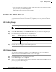
Chapter 3 Building the Network 3.6.2 Overview of Supported Links Table 3-9 Supported NE Links (continued) NE Model NE Card Physical ONS 15305 STM-1 X X STM-4 X X STM-16 X X ONS 15310 ONS 15327 OTS OMS OCH SONET/SDH PoS X CTX (OC-3 port) X X CTX (OC-12 port) X X OC-3/STM-1 X X OC-12/STM-4 X X OC-48/STM-16 X X E10/100-4 X G1000-2 X ONS 15454 SONET and OPT-BST ONS 15454 SDH 32MUX-O X 32DMX-O X 4MD-xx.x X AD-1C-xx.x X AD-2C-xx.x X AD-4C-xx.
Chapter 3 Building the Network 3.6.2 Overview of Supported Links Table 3-9 Supported NE Links (continued) NE Model NE Card Physical ONS 15530 Nonsplitter 2.5 Gbps ITU Trunk X X Nonsplitter 10 Gbps ITU Trunk X X Splitter 10 Gbps ITU Trunk X X 10 Gbps Uplink X OADM X Type 1 single-mode Transponder xx.x X X Type 1 multi-mode Transponder xx.x X X Type 2 extended range Transponder xx.x X X 10 GE Transponder xx.x X X OADM xx.
Chapter 3 Building the Network 3.6.3 Viewing the Link Table Table 3-9 Supported NE Links (continued) NE Model NE Card Physical ONS 15808 TT/RT X Mux/Demux X Amp X X BCS-LH X X BCS-ELH X X 16-OC48 X 4-OC192 X 1-OC768 X 8x10GE X 16-OC48 X 4-OC192 X 1-OC768 X 8x10GE X Supports links with CTC-based NEs and unmanaged NEs X CRS-1 XR 12000 MDS 9000 OTS OMS OCH SONET/SDH Layer 2 X X 3.6.
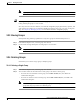
Chapter 3 Building the Network 3.6.3 Viewing the Link Table Table 3-10 describes the fields in Link table. Table 3-10 Field Descriptions for the Link Table Field Description Link Alarm Severity Highest severity alarm associated with the selected link. Link Source ID ID of the link source. Link Source PTP PTP of the link source. Link Destination ID ID of the link destination. Link Destination PTP PTP of the link destination.
Chapter 3 Building the Network 3.6.3 Viewing the Link Table Table 3-10 Field Descriptions for the Link Table (continued) Field Description Is Link Valid Validity of the link. Values are Valid or Invalid. For autodiscovered links, the value is Valid if both the terminating NEs are in service and the NEs are able to confirm the presence of the link.
Chapter 3 Building the Network 3.6.4 Filtering the Link Table Table 3-10 Field Descriptions for the Link Table (continued) Field Description Shared Risk Link Groups (SONET/SDH layer rates only) Free-format string that represents the shared risk link group (SRLG), or a group of links that share a common risk. For example, a set of links that originate at a node share the node as the common risk. SRLGs allow you to classify links into logical groups.
Chapter 3 Building the Network 3.6.6 Creating Links • OMS • OCH • SONET/SDH • Layer 2 • Layer 3 When you customize the location of the NE icons in the Network Map, make sure to take account of the NEs that you cannot see due to the layer rate that you selected. If you customize the map on one layer rate and then change the layer rate, NE icons and links might overlap because of the layer rate discrepancies. Note 3.6.
Chapter 3 Building the Network 3.6.6 Creating Links Note The layer details displayed in the link creation wizard are based on the NE selected as source of the link. For example, when you attempt to create a link from NE A to NE B, the link sizes displayed are based on the supported sizes and inventory of NE A. If the link is attempted in the reverse direction, from NE B to NE A, the link sizes displayed is based on the inventory and size support for NE B.
Chapter 3 Building the Network 3.6.6 Creating Links Note f. A PTP can be associated with only one bidirectional link or two unidirectional links at a particular layer rate for all NEs except Not Managed/Other Vendor NEs. For Not Managed/Other Vendor NEs, a PTP can terminate in only one link. Click Next. Step 3 The Link Summary panel summarizes the attributes of the new link. To change the link summary information, click Back and change the selections as needed. Step 4 Click Finish.
Chapter 3 Building the Network 3.6.6 Creating Links Table 3-12 Field Descriptions for the Create Link Wizard (continued) Field Description Direction Specify whether the link is unidirectional or bidirectional. For the ONS 15501, ONS 15800, ONS 15801, and ONS 15808, only unidirectional links are available. Provision Type Specify the type of link provisioning. Values are: • Manual—The link is manually provisioned.
Chapter 3 Building the Network 3.6.7 Modifying Links Table 3-12 Field Descriptions for the Create Link Wizard (continued) Field Description Name For the ONS 15501, ONS 15530, and ONS 15540, identify the PTP as a single name, which includes a port type and slot number and might also include a subslot number and port number. Link Summary Panel Link Summary Note Summarizes the selections you made. To change the Link Summary, click Back and change your selection(s).
Chapter 3 Building the Network 3.6.7 Modifying Links Table 3-14 describes the fields in the Modify Link wizard. Note Open the Modify Link wizard using one of the following methods: Step 1 • In the Link table, select a link and choose Edit > Modify Link. • In the Network Map, select a link and choose Configuration > Modify Link.
Chapter 3 Building the Network 3.6.8 Deleting Links Table 3-14 Field Descriptions for the Modify Link Wizard (continued) Field Description Shared Risk Link Groups (SONET/SDH layer rates only) Modify the strings that represent the SRLG. The SRLG attribute supports up to 5 comma-separated values, with 32 characters per value. Link Summary Panel Link Summary Summarizes the changes you made to the editable fields. To change the Link Summary, click Back and change your selection(s). 3.6.
Chapter 3 Building the Network 3.6.10 Filtering the Link Utilization Table Depending on the number of provisioned circuits, the consumed bandwidth is totaled. Circuits such as VAP/LAP and virtual tributary (VT) tunnel are preprovisioned and are not included in the calculation. This is applicable to SONET and SDH. Example: In SDH, for a STM4 link, the total bandwidth is (4 x 155) Mbps, where STM-1 = 155 Mbps.
Chapter 3 Building the Network 3.7 How Do I Use Network Maps? Table 3-16 Field Descriptions for the Link Utilization Table Filter Dialog Box Payload Type Description SONET You can filter on the STS ID to see circuits going through that STS only. Select All to see all the tributaries on that link. SDH You can filter on specific VC4, VC3/TUG3, and TUG2 IDs. The ALL option shows all tributaries. The None option is available on VC3/TUG3 and TUG2.
Chapter 3 Building the Network 3.7.1 Customizing a Network Map Step 2 Use the Edit menu in the Network Map window to customize the Network Map. Edit menu options include: • Enable Drag—Enables the drag-and-drop functionality. • Enable Offview—Enables the display of off-view icons in the selected Network Map window. If an NE has a link to an NE on a different map, the off-view NE is represented by an off-view icon.
Chapter 3 Building the Network 3.7.2 Viewing a Node in the Network Map c. In the Domain Management area, click the Truncate Network Map Node Name First Characters or Truncate Network Map Node Name End Characters radio button. d. Click Save. 3.7.2 Viewing a Node in the Network Map Icons in the Network Map are displayed based on the nodes you select in the Domain Explorer or Subnetwork Explorer.
Chapter 3 Building the Network 3.7.4 Modifying a Node Icon or a Map Background Image 3.7.4 Modifying a Node Icon or a Map Background Image Network map backgrounds are provided by default as part of CTM, and are used to display a geographical layout of the network. The icons in the Network Map can be customized. See Appendix A, “Icons and Menus Displayed in CTM” for details of all the icons displayed in this window.
Chapter 3 Building the Network 3.7.5 Saving Changes to the Network Map find an icon in an unexpected position, the object most likely was never positioned manually and saved and was therefore positioned automatically. To fix the icon location, manually move the object to the correct position and save the map. 3.7.5 Saving Changes to the Network Map Step 1 In the Domain Explorer or Subnetwork Explorer tree, click a node and choose File > Network Map.
Chapter 3 Building the Network 3.8.1 Discovering CTC-Based NEs Note The Discovered Network Elements group can be viewed only by users who have all NEs assigned to them. Therefore, in the Add New NE wizard, the grouping option “Group discovered NEs in the Discovered Network Elements Group” is not available. 3.8.1 Discovering CTC-Based NEs When a CTC-based NE is added as a GNE, all NEs that are DCC-connected to the GNE are automatically discovered. The discovered NEs are added automatically to CTM.
Chapter 3 Building the Network 3.8.3 Rediscovering ONS 155xx, CRS-1, and XR 12000 NEs all types of discovery: periodic rediscovery, user-requested rediscovery, and update-triggered discovery. To view the table, choose Configuration > ONS 155XX > Discovery Info Table in the Domain Explorer. Table 3-17 describes the fields in the Discovery Information table.
Chapter 3 Building the Network 3.8.4 Resetting the Resync Interval Note Step 2 To rediscover all ONS 155xx, CRS-1, or XR 12000 NEs in the network, choose Configuration > ONS 155XX, Cisco CRS-1, or Cisco XR 12000 > Rediscover All. Note Step 3 This command is unavailable unless at least one NE in the selection is in the In Service or Under Maintenance state. This command is unavailable unless at least one NE in the network is in the In Service or Under Maintenance state.
Chapter 3 Building the Network 3.9 How Do I Discover the Network for MGX Voice Gateway Devices? • Routing table and protocol information Step 1 In the Domain Explorer window, choose Administration > Control Panel. Step 2 Expand NE Service. Step 3 Select an NE and change the Resync Interval field in the Resync Scheduling area. Step 4 Click Save. 3.
Chapter 3 Building the Network 3.9.1 Discovering NEs 3.9.1 Discovering NEs The network discovery service in CTM collects information from individual NEs, discovers new NEs added to the network, and computes network-level information, such as physical topology and discrepancies. When you add a new NE to CTM, the discovery process starts. When the process finishes, all of the NE information (such as inventory, configuration, physical topology, and discrepancies) is collected and CTM is updated. 3.
Chapter 3 Building the Network 3.10.
Chapter 3 Building the Network 3.10.1 Synchronization Settings for the ONS 15310, ONS 15327, ONS 15454 SONET, and ONS 15600 SONET • Step 4 In the BITS Facilities section of the General subtab, complete the following information: Note Step 5 Quality of RES—If the timing source supports the reserved S1 byte, set the timing quality here. (Most timing sources do not use RES.) Qualities are displayed in descending quality order as ranges.
Chapter 3 Building the Network 3.10.1 Synchronization Settings for the ONS 15310, ONS 15327, ONS 15454 SONET, and ONS 15600 SONET – Timing Mode set to Line—Options are the node’s working OC-N cards (non-DWDM nodes), OSC cards (DWDM nodes), and Internal Clock. Select the cards/ports that are directly or indirectly connected to the node wired to the BITS source; that is, the node’s trunk (span) cards. Set Reference 1 to the trunk card that is closest to the BITS source.
Chapter 3 Building the Network 3.10.1 Synchronization Settings for the ONS 15310, ONS 15327, ONS 15454 SONET, and ONS 15600 SONET Step 1 Select an ONS 15310, ONS 15327, ONS 15454 SONET, or ONS 15600 SONET NE and choose Configuration > NE Explorer. Step 2 In the node property pane, click the Timing tab. Fields shown depend on the NE that is selected. Step 3 In the General Timing section of the General subtab, enter the following information: Step 4 Step 5 • Timing Mode—Set to External.
Chapter 3 Building the Network 3.10.2 Synchronization Settings for the ONS 15454 SDH and ONS 15600 SDH 3.10.2 Synchronization Settings for the ONS 15454 SDH and ONS 15600 SDH SSM communicates information about the quality of the timing source. SSM messages are carried on the S1 byte of the SDH section overhead. These messages enable SDH devices to automatically select the highest quality timing reference and to avoid timing loops. SSM messages are either Generation 1 or Generation 2.
Chapter 3 Building the Network 3.10.2 Synchronization Settings for the ONS 15454 SDH and ONS 15600 SDH Step 4 • Revertive—If checked, the NE reverts to a primary reference source after the conditions that caused it to switch to a secondary timing reference are corrected. • Reversion Time—If Revertive is checked, indicate the amount of time the NE will wait before reverting to its primary timing source. • SSM Message Set (Applicable to the ONS 15600 SDH)—Enabled only if T1 signal type is selected.
Chapter 3 Building the Network 3.10.2 Synchronization Settings for the ONS 15454 SDH and ONS 15600 SDH Note • Reference lists define up to three timing references for the node and up to six BITS Out references. BITS Out references define the timing references used by equipment attached to the node’s MIC-C/T/P FMEC Timing A Out and Timing B Out connectors.
Chapter 3 Building the Network 3.10.2 Synchronization Settings for the ONS 15454 SDH and ONS 15600 SDH Note Refer to the Cisco ONS 15454 SDH Troubleshooting Guide or Cisco ONS 15600 SDH Troubleshooting Guide for timing-related alarms. 3.10.2.2 Setting Up Internal Timing for CTC-Based SDH NEs If no BITS source is available, you can set up internal timing by timing all nodes in the ring from the internal clock of one node. Caution Internal timing is Stratum 3 and not intended for permanent use.
Chapter 3 Building the Network 3.11 How Do I Synchronize the Network for MGX Voice Gateway Devices? Step 6 Click Apply. Step 7 In the Domain Explorer tree, select the node that will be timed from the node that was set up in Steps 1 through 7 and choose Configuration > NE Explorer. Step 8 In the Timing tab, complete the following: • In the General Timing section of the General subtab: – Timing Mode—Set to Line. – Revertive—Not applicable for internal timing; the default setting is sufficient.
Chapter 3 Building the Network 3.11.1 Viewing Clocking Sources 3.11.1.1 Configuring Global Clocking Step 1 In the Domain Explorer tree, select the node and choose Configuration > MGX Voice Gateway > Configuration Center. Step 2 Drag and drop the node from the Hierarchy pane to the right-most pane. Step 3 Click the Elements tab to display the Configuration Window for Elements. Step 4 Click the Clocking tab to display the Global Clocking Configuration window.
Chapter 3 Building the Network 3.12 How Do I Test Connectivity for Optical and Routing Devices? 3.11.1.4 Creating a Manual Clock Source To create a manual clock source: Step 1 In the Domain Explorer, right-click the PNNI node from the Hierarchy pane and choose Configuration Center. Step 2 Click the Elements tab to display the Configuration Window for Elements. Step 3 Click the Clocking tab to display Clocking Configuration window.
Chapter 3 Building the Network 3.12.1 Pinging an NE 3.12.1 Pinging an NE Step 1 In the Domain Explorer tree, select the NE to ping. Step 2 Choose Fault > Ping NE. The ping results include round-trip time and packet loss statistics. Step 3 Click OK in the dialog box. Note This function is enabled if the operational state of the NE is In Service or Under Maintenance. It is disabled if the operational state of the NE is Out of Service or Preprovisioned.
Chapter 3 Building the Network 3.13 How Do I Test Connectivity for MGX Voice Gateway Devices? Testing NE connectivity occurs at the management protocol level (SNMP or CORBA). Step 1 In the Domain Explorer tree, select the MGX node and choose Fault > MGX Voice Gateway > Diagnostic Center. Step 2 Click the Manageability tab to display the node login information. Step 3 Enter the Service Level username and password. Step 4 Click Check Manageability.