A P P E N D I X A Maintenance and Upgrade Procedures This appendix describes how to install and replace the Cisco Security Services Modules (SSM), the chassis cover, the power supply, and the CompactFlash.
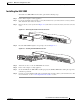
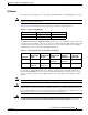
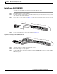
Appendix A Maintenance and Upgrade Procedures Installing and Replacing the 4GE SSM Overview Figure A-1 lists the 4GE SSM ports and LEDs. Figure A-1 4GE SSM Ports and LEDs 3 2 2 1 8 0 SPD 132983 LNK 3 7 Cisco SSM-4GE 4 1 Note 5 6 1 RJ-45 ports 2 RJ-45 Link LED 3 RJ-45 Speed LED 4 Power LED 5 Status LED 6 SFP ports 7 SFP Link LED 8 SFP Speed LED Figure A-1 shows SFP modules installed in the ports slots.
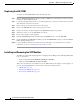
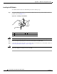
Appendix A Maintenance and Upgrade Procedures Installing and Replacing the 4GE SSM Installing the 4GE SSM To install a new 4GE SSM for the first time, perform the following steps: Step 1 Power off the adaptive security appliance. Step 2 Locate the grounding strap from the accessory kit and fasten it to your wrist so that it contacts your bare skin. Attach the other end to the chassis. Step 3 Remove the two screws (as shown in Figure A-2) at the left rear end of the chassis, and remove the slot cover.
Appendix A Maintenance and Upgrade Procedures Installing and Replacing the 4GE SSM Replacing the 4GE SSM To replace an existing 4GE SSM, perform the following steps: Step 1 Enter the hw-mod mod 1 shut command in privileged EXEC mode. Verify that the module is down by making sure that the LEDs are all off. Step 2 Locate the grounding strap from the accessory kit and fasten it to your wrist, so that it contacts your bare skin. Attach the other end to the chassis.
Appendix A Maintenance and Upgrade Procedures Installing and Replacing the 4GE SSM SFP Module The adaptive security appliance uses a field-replaceable SFP module to establish Gigabit connections. Note If you install an SFP module after the switch has powered on, you must reload the adaptive security appliance to enable the SFP module. Table A-2 lists the SFP modules that are supported by the adaptive security appliance.
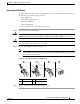
Appendix A Maintenance and Upgrade Procedures Installing and Replacing the 4GE SSM Installing the SFP Module To install the SFP module in the 4GE SSM, perform the following steps: Step 1 Line up the SFP module with the port and slide the SFP module into the port slot until it locks into position as shown in Figure A-4.
Appendix A Maintenance and Upgrade Procedures Installing and Replacing the 4GE SSM Removing the SFP Module The SFP modules have different types of latching devices used to detach the SFP module from a port. The following are the different types of modules: • Mylar Tab Module • Actuator/Button SFP Module • Bale-Clasp SFP Module • Plastic Collar Module To remove the SFP module, perform the following steps: Step 1 Warning Caution Step 2 Disconnect all cables from the SFP.
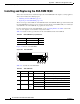
Appendix A Maintenance and Upgrade Procedures Installing and Replacing the ASA SSM 10/20 Installing and Replacing the ASA SSM 10/20 This section describes how to install and replace the ASA SSM 10/20 in the adaptive security appliance. This section includes the following topics: • Installing an ASA SSM 10/20, page A-9 • Replacing an ASA SSM 10/20, page A-10 There are two types of the SSM: the ASA SSM 10 and the ASA SSM 20.
Appendix A Maintenance and Upgrade Procedures Installing and Replacing the ASA SSM 10/20 Installing an ASA SSM 10/20 To install a new ASA SSM for the first time, perform the following steps: Step 1 Power off the adaptive security appliance. Step 2 Locate the grounding strap from the accessory kit and fasten it to your wrist so that it contacts your bare skin. Attach the other end to the chassis.
Appendix A Maintenance and Upgrade Procedures Removing and Replacing the Chassis Cover Replacing an ASA SSM 10/20 To replace an existing ASA SSM, perform the following steps: Step 1 Enter the hw-mod mod 1 shut command in privileged EXEC mode. Verify if the module is down by checking the LEDs. Step 2 Locate the grounding strap from the accessory kit and fasten it to your wrist so that it contacts your bare skin. Attach the other end to the chassis.
Appendix A Maintenance and Upgrade Procedures Removing and Replacing the Chassis Cover Step 3 Remove the screws from the top of the chassis (Figure A-9). Figure A-9 Removing the Top Panel Screws CISCO ASA 5540 SERIES POWER STATUS ACTIVE VPN Step 4 119635 Adaptive Security Appliance FLASH Pull the top panel up as shown in Figure A-10. Put the panel in a safe place.
Appendix A Maintenance and Upgrade Procedures Removing and Replacing the Chassis Cover Replacing the Chassis Cover Caution Do not operate the adaptive security appliance without the chassis cover installed. The chassis cover protects the internal components, prevents electrical shorts, and provides proper air-flow for cooling the electronic components. To replace the chassis cover, perform the following steps: Step 1 Place the chassis on a secure surface with the front panel facing you.
Appendix A Maintenance and Upgrade Procedures Working in an ESD Environment Working in an ESD Environment Electrostatic discharge (ESD) can damage equipment and impair electrical circuitry. ESD damage occurs when electronic components are improperly handled and can result in complete or intermittent failures. Always follow ESD-prevention procedures when you remove and replace components. Ensure that the chassis is electrically connected to earth ground.
Appendix A Maintenance and Upgrade Procedures Removing and Replacing the Power Supply Step 6 Lift the rear of the chassis from the surface and unscrew both the screws that secures the power supply to the chassis, as shown in Figure A-13. Figure A-13 Removing the Power Supply Screws S E A FL N P V R TIV E A C S 119581 P O W TA TU S H FLASH 1 1 Chassis bottom Step 7 Locate the power connector on the system board.
Appendix A Maintenance and Upgrade Procedures Removing and Replacing the Power Supply Step 9 Remove the power supply brace by pulling it up and then out as shown in Figure A-15. Figure A-15 Removing the Power Supply 4 119578 3 2 1 Step 10 1 Back panel 3 Power supply brace 2 Power supply 4 Front panel From the back of the chassis, push the power supply forward, and then lift it up and out.
Appendix A Maintenance and Upgrade Procedures Removing and Replacing the Power Supply Replacing the AC Power Supply To replace the AC power supply, perform the following steps: Step 1 Insert the new power supply into place and slide it towards the back of the adaptive security appliance. Step 2 Lift the rear of the adaptive security appliance from the surface and reinstall both screws. Step 3 Insert the power supply brace and press down until it fits into place, as shown in Figure A-16.
Appendix A Maintenance and Upgrade Procedures Installing the DC Model Installing the DC Model Warning Note Before performing any of the following procedures, ensure that power is removed from the DC circuit. To ensure that all power is OFF, locate the circuit breaker on the panel board that services the DC circuit, switch the circuit breaker to the OFF position, and tape the switch handle of the circuit breaker in the OFF position.
Appendix A Maintenance and Upgrade Procedures Installing the DC Model Step 6 The adaptive security appliance is equipped with two grounding holes at the side of the chassis, which you can use to connect a two-hole grounding lug to the adaptive security appliance. Use 8-32 screws to connect a copper standard barrel grounding lug to the holes. The adaptive security appliance requires a lug where the distance between the center of each hole is 0.56 inches.
Appendix A Maintenance and Upgrade Procedures Removing and Replacing the CompactFlash Step 11 Replace the DC power supply plastic shied. Step 12 Power on the adaptive security appliance from the switch at the rear of the chassis. Note If you need to power cycle the DC adaptive security appliance, wait at least 5 seconds between powering off the adaptive security appliance and powering it back on.
Appendix A Maintenance and Upgrade Procedures Removing and Replacing the CompactFlash Step 6 Carefully slide the CompactFlash out of its connector as shown in Figure A-19. The CompactFlash has a lip on its lower edge, which you can use to grip the CompactFlash. Otherwise, use sliding pressure with your thumb or finger to slide the CompactFlash out of its connector.
Appendix A Maintenance and Upgrade Procedures Removing and Replacing the CompactFlash Replacing the System CompactFlash To replace the system CompactFlash, perform the following steps: Step 1 Align the new system CompactFlash with the connector on the riser card. Step 2 Push the system CompactFlash inward until it is fully seated in the connector, see Figure A-20. Figure A-20 Replacing the System CompactFlash 114004 1 1 System CompactFlash Step 3 Replace the adaptive security appliance cover.
Appendix A Maintenance and Upgrade Procedures Removing and Replacing the CompactFlash Removing the User CompactFlash To remove the user CompactFlash, perform the following steps: Step 1 Locate the user CompactFlash in its slot in the rear panel of the chassis. Step 2 Press the release button to eject the card. See Figure A-21.
Appendix A Maintenance and Upgrade Procedures Removing and Replacing the CompactFlash Replacing the User CompactFlash To replace the user CompactFlash, perform the following steps: Step 1 Locate the user CompactFlash slot in the rear panel of the chassis. See Figure A-22.
Appendix A Maintenance and Upgrade Procedures Removing and Replacing the CompactFlash Cisco ASA 5500 Series Hardware Installation Guide A-24 78-16409-03