C H A P T E R 2 Installing a PIX Firewall The following sections in this chapter describe how to install a PIX Firewall: • Installation Overview • Before You Begin the Installation • Installing a PIX 506 • Installing a PIX 515 • Installing a PIX 525 • Installing a PIX 520 or Earlier Model • Startup Messages • Software Installation Notes Installation Overview Follow these steps to install a PIX Firewall: Note Step 1 If your PIX Firewall model supports a failover configuration, perform th
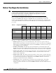
Chapter 2 Installing a PIX Firewall Before You Begin the Installation Before You Begin the Installation Note The information you gather here is required during configuration and is a reminder to find it while installing your PIX Firewall—before beginning the configuration. You can use this information with Chapter 9, “Installing the PIX Firewall Setup Wizard” or with the Cisco PIX Firewall Configuration Guide, Version 5.2.
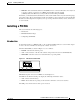
Chapter 2 Installing a PIX Firewall Installing a PIX 506 • MTU size—The maximum transmission unit (MTU) size for each network interface. You only need to specify a value if you want to set an MTU size that differs from the default (1,500 bytes/block for Ethernet; 8,192 bytes/block for Token Ring and FDDI). In addition, you should determine the IP address of the outside default router and your network topology and security policy.
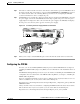
Chapter 2 Installing a PIX Firewall Installing a PIX 506 Figure 2-2 PIX 506 Back Panel ACT(ivity) LED ACT(ivity) LED LINK LINK LED LED Power switch DC POWER INPUT LINK ACT ETHERNET 1 LINK ETHERNET 0 10BaseT (RJ-45) USB 38852 ACT CONSOLE 10BaseT USB (RJ-45) port Console port (RJ-45) PIX 506 Installation Steps The PIX 506 should be placed on a flat, stable surface. The PIX 506 is not rack mountable.
Chapter 2 Installing a PIX Firewall Installing a PIX 506 Step 2 The inside or outside network connections can be made to either interface port on the PIX 506. Connect the inside network cable to the interface connector marked ETHERNET 0 or ETHERNET 1. Connect the outside network cable to the remaining Ethernet port. Refer to the “Configuring the PIX 506” section for information on how to configure the ports. Step 3 The PIX 506 uses an external AC to DC power supply.
Chapter 2 Installing a PIX Firewall Installing a PIX 515 Installing a PIX 515 This section includes the following topics: • Introduction • Mounting the PIX 515 • PIX 515 Installation Steps • Configuring the PIX 515 • PIX 515 Feature Licenses Introduction To download software to a PIX Firewall, see the “Software Installation Notes” section in this chapter or refer to the Cisco PIX Firewall Configuration Guide, Version 5.2.
Chapter 2 Installing a PIX Firewall Installing a PIX 515 Refer to Figure 2-6 for a display of the controls and connectors on the PIX 515 back panel.
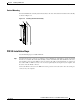
Chapter 2 Installing a PIX Firewall Installing a PIX 515 Mounting the PIX 515 The PIX 515 can be mounted in a rack, on a wall, or on a flat surface. If you do not wish to rack mount the unit, attach the rubber feet to the bottom of the unit as shown in Figure 2-7.
Chapter 2 Installing a PIX Firewall Installing a PIX 515 Vertical Mounting To mount the PIX 515 vertically, attach the brackets to the side of the unit and mount the unit vertically as shown in Figure 2-8.
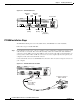
Chapter 2 Installing a PIX Firewall Installing a PIX 515 PIX 515 Serial Console Cable PIX-515 Figure 2-9 100 Mbps Link FAILOVER FDX 10/100 ETHERNET 0 CONSOLE Computer serial port DB-9 or DB-25 Console port (RJ-45) Step 2 29226 RJ-45 to DB-9 or DB-25 serial cable (null-modem) If your unit has a four-port Ethernet card already installed, refer to Figure 2-10. (The four-port interface card requires the PIX-515-UR license to be accessed.
Chapter 2 Installing a PIX Firewall Installing a PIX 515 As shown in Figure 2-11, if your unit has one or two single-port Ethernet cards installed in the auxiliary assembly on the left of the unit at the rear, the cards are numbered top to bottom so that the top card is Ethernet 2 and the bottom card is Ethernet 3. (Additional interface cards require the PIX-515-UR license to be accessed.
Chapter 2 Installing a PIX Firewall Installing a PIX 525 Note If for any reason you may choose to downgrade to any software version, note that you need to use the clear flashfs command before doing so. A new section has been added to Flash memory that must be cleared before downgrading.
Chapter 2 Installing a PIX Firewall Installing a PIX 525 • ACT—On when the unit is the Active failover unit. If failover is present, the light is on when the unit is the Active unit and off when the unit is in Standby mode. 44568 Figure 2-14 PIX 525 Front Panel LEDs There are three LEDs for the each RJ-45 interface port and three types of fixed interface connectors on the back of the PIX 525. The LEDs and connectors are shown in Figure 2-15.
Chapter 2 Installing a PIX Firewall Installing a PIX 525 • LINK—Shows that data is passing through that interface. The following are fixed connectors on the back of the PIX 525: • RJ-45—Network and console connectors. • DB-15—Failover cable connector. • USB—Not used at the present time. PIX 525 Installation Steps Use the following steps to install a PIX 525: Step 1 Step 2 The PIX 525 provides one set of brackets for installing the unit in an equipment rack.
Chapter 2 Installing a PIX Firewall Installing a PIX 525 Step 3 The inside or outside network connections can be made to any available interface port on the PIX 525. If you are only using the ETHERNET 0 and ETHERNET 1 ports, connect the inside network cable to the interface connector marked ETHERNET 0 or ETHERNET 1. Connect the outside network cable to the remaining Ethernet port. Refer to “Configuring the PIX 525” for information on how to configure the ports.
Chapter 2 Installing a PIX Firewall Installing a PIX 520 or Earlier Model PIX 525 Feature Licenses If you have a PIX-525-UR unrestricted feature license, the following options are available: • Note Note If you have a second PIX 525 to use as a failover unit, install the failover feature and cable as described in Chapter 3, “Installing Failover.” Do not power on the failover units until the primary unit has been configured.
Chapter 2 Installing a PIX Firewall Installing a PIX 520 or Earlier Model Figure 2-17 PIX 520 Front, Rear, and Side Panels.
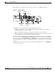
Chapter 2 Installing a PIX Firewall Installing a PIX 520 or Earlier Model Figure 2-18 lists the controls on earlier PIX Firewall models. Figure 2-18 Earlier PIX Firewall Access Power light Diskette drive Power switch H7484 POWER RESET Reset switch Step 2 Diskette eject button Connect network cables to each of the PIX Firewall’s network interfaces. On the PIX 520, connect the cables at the front of the unit; on earlier models, connect the cables at the rear.
Chapter 2 Installing a PIX Firewall Installing a PIX 520 or Earlier Model PIX Firewall with a Four-Port Interface Card As of PIX Firewall version 4.4(1) and later, you can install one optional four-port Ethernet interface card in the PIX 520 and earlier hardware models. Note Use of the four-port card changes the position of the outside and inside interfaces depending on the slot in which the card is installed. Four-port Ethernet card connectors are numbered from the top connector down sequentially.
Chapter 2 Installing a PIX Firewall Installing a PIX 520 or Earlier Model Figure 2-21 shows how the slots are numbered if a single-port interface card is inserted in slot 0 and a four-port interface card is inserted in slot 1.
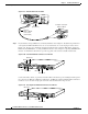
Chapter 2 Installing a PIX Firewall Installing a PIX 520 or Earlier Model Figure 2-23 PIX Firewall Serial Cable Assembly PIX security appliance console connector C O N S O L E Console port (DB-9) Computer serial port DB-25 or DB-9 12275 DB-9-to-DB-25 serial cable (null-modem) Step 3 Connect one of the DB-9 serial connectors to the console connector on the front panel of the PIX Firewall. Step 4 Connect one end of the RJ-45 null modem cable to the DB-9 connector.
Chapter 2 Installing a PIX Firewall Startup Messages To configure your unit, refer to the Cisco PIX Firewall Configuration Guide, Version 5.2, which is available in your accessory kit or online at the following site: http://www.cisco.com/en/US/products/sw/secursw/ps2120/products_configuration_guide_book09186 a00801027d5.html Always check the release notes first before configuring the PIX Firewall for the latest release details.
Chapter 2 Installing a PIX Firewall Startup Messages The Flash statement indicates the type of Flash memory. Use the show version command in the Configuration Guide for the Cisco Secure PIX Firewall Version 5.2 to verify the amount of Flash memory. If you have an insufficient amount of memory, the PIX Firewall would have displayed an error message and stopped the installation. Refer to Chapter 1, “Introduction,” for a description of the system requirements for the PIX Firewall platforms.
Chapter 2 Installing a PIX Firewall Startup Messages PIX Firewall then lists each interface. Because PIX Firewall interface cards are polled instead of using interrupts, the IRQ (interrupt request) lines can have duplicate numbers: mcwa mcwa mcwa mcwa i82559 i82559 i82558 i82558 Ethernet Ethernet Ethernet Ethernet at at at at irq 10 irq 7 irq 11 irq 11 MAC: MAC: MAC: MAC: 0050.54fe.eaea 0050.54fe.eaeb 00e0.b600.4520 00e0.b600.4521 In this example, the PIX Firewall has four Ethernet interfaces.
Chapter 2 Installing a PIX Firewall Startup Messages If you have an activation key that supports encryption, the following statement appears: ****************************** Warning ******************************* Compliance with U.S. Export Laws and Regulations - Encryption. This product performs encryption and is regulated for export by the U.S. Government.
Chapter 2 Installing a PIX Firewall Startup Messages Writing Different Versions of the Configuration to Flash Memory If the Flash memory version and the version of the installation software differ, PIX Firewall automatically writes the image to Flash memory. The following is an example of the message that is displayed when the Flash memory and the installation software are different versions: Flash version 5.2(0), Install version 5.
Chapter 2 Installing a PIX Firewall Startup Messages The example startup messages continue: Received nnnnnnn bytes. Flash version 5.2(0), Install version 5.2(1) Installing to flash Serial Number:nnnnnnn (0xnnnnn) Activation Key:70ffbacc 62b8e7c2 87021a9c 98c9a02b Do you want to enter a new activation key? [n] Writing nnnnnnn bytes image into flash... Ready to reboot, please remove the disk.
Chapter 2 Installing a PIX Firewall Software Installation Notes Software Installation Notes This section provides information about installing software on a PIX Firewall. Note If you are upgrading from an earlier software version, save your configuration and write down your activation key.
Chapter 2 Installing a PIX Firewall Software Installation Notes Step 4 If you are using Windows, use the rawrite program to put the Boothelper image on diskette. A sample rawrite session follows: C:\pix> rawrite RaWrite 1.2 - Write disk file to raw floppy diskette Enter source file name: bh521.bin Enter destination drive: a: Please insert a formatted diskette into drive A: and press -ENTER- : Number of sectors per track for this disk is 18 Writing image to drive A:. Press ^C to abort.
Chapter 2 Installing a PIX Firewall Software Installation Notes The following is an example session: Cisco Secure PIX Boothelper Version 5.2(1) pixboothelper> a 10.132.12.66 address:10.132.12.66 pixboothelper> s 10.129.0.2 server 10.129.0.2 pixboothelper> i 0 current interface is 0 0: i82557 @ PCI(bus:0 dev:13 irq:11) ethernet0 100basetx 1: i82557 @ PCI(bus:0 dev:14 irq:10) ethernet1 not_init 2: i82557 @ PCI(bus:0 dev:15 irq:15) ethernet2 not_init pixboothelper> f pix-5.2.1-release file pix-5.2.
Chapter 2 Installing a PIX Firewall Software Installation Notes Note A diskette software image is not included with the PIX 506, PIX 515, or PIX 525. The initial image is stored in Flash memory. You can obtain the latest binary image from Cisco Connection Online (CCO) using a web browser or via FTP, storing the image on a TFTP server.
Chapter 2 Installing a PIX Firewall Software Installation Notes If the command is used without the location or pathname optional parameters, then the location and filename are obtained from the user interactively via a series of questions similar to those presented by Cisco IOS software. If you only enter a colon (:), parameters are taken from the tftp-server command settings.
Chapter 2 Installing a PIX Firewall Software Installation Notes The next example takes the information from the tftp-server command. In this case, the TFTP server is in an intranet and resides on the outside interface. The example sets the filename and location from the tftp-server command, saves memory, and then downloads the image to Flash memory: tftp-server outside 10.1.1.5 pix521.bin Warning: 'outside' interface has a low security level (0). write memory Building configuration...
Chapter 2 Installing a PIX Firewall Software Installation Notes Follow these steps to download an image over TFTP using the monitor command: Step 1 Immediately after you power on the PIX Firewall and the startup messages appear, send a BREAK character or press the Esc (Escape) key. Note If you are using HyperTerminal with Windows 95, you can press ctrl-break to activate a BREAK or press the Esc (Escape) key.
Chapter 2 Installing a PIX Firewall Software Installation Notes The following is an example of the download screen display: Rebooting.... PIX BIOS (4.0) #47: Sat May 8 10:09:47 PDT 2000 Platform PIX-520 Flash=AT29C040A @ 0x300 Use BREAK or ESC to interrupt flash boot. Use SPACE to begin flash boot immediately. Flash boot interrupted. 0: i8255X @ PCI(bus:0 dev:13 irq:11) 1: i8255X @ PCI(bus:0 dev:14 irq:10) Using 1: i82558 @ PCI(bus:0 dev:14 irq:10), MAC: 0090.2722.f0b1 Use? for help.
Chapter 2 Installing a PIX Firewall Software Installation Notes TFTP Download Error Codes During a TFTP download, if tracing is on, non-fatal errors appear in the midst of dots that display as the software downloads. The error code appears inside angle brackets. For example, random bad blocks would appear as follows: ....<11>..<11>.<11>......<11>... Also, tracing will show “A” and “T” for ARP and timeouts, respectively. Receipt of non-IP packets causes the protocol number to display inside parentheses.
Chapter 2 Installing a PIX Firewall Software Installation Notes Upgrading the Activation Key Note The activation key can only be entered after downloading a new image—not from the command line or without first rebooting. Note You must have a new activation key before you can use IPSec features or commands. You can have a new activation key sent to you by completing the form at the following site, provided you are a registered Cisco user: https://www.cisco.com/cgi-bin/Software/FormManager/formgenerator.
Chapter 2 Installing a PIX Firewall Software Installation Notes Installation Guide for the Cisco Secure PIX Firewall Version 5.