Quick Start Guide Is Cisco documentation helpful? Click here or go to http://www.cisco.com/warp/public/732/docsurvey/rtg/ to give us your feedback.
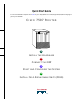
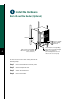
Install the Hardware Captive installation screw DC AC FA IL PO WE R EN NO AB RM LE AL Upper power supply Chassis grounding receptacles EJ EC T SL SLO OT T 0 1 I SL MA AV ST E ER O SL AV E/M AS TE R Captive installation screw CP U HA LT EN AB RE LE SE T DC AC FA IL PO WE H3888 R Lower power supply AU X.
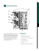
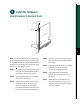
Install the Hardware Prepare to Install the Router Note For detailed hardware installation instructions and safety guidelines, refer to the Cisco 7500 Series Router Installation and Configuration Guide, Site Preparation and Safety Guide, and the Cisco 7500 Regulatory Compliance and Safety Guide.
Install the Hardware Install the Router DC AC FAIL POW NO ER EN RM AB LE AL EJ EC T SL SLOT OT 0 1 I SL MAST AV E ER O SL AV E/M CP RE DC AC AS U TE HA SE R LT EN AB LE T FAIL POW ER AU I NS X. OL E ROUTE SWITCH PROCESSOR 2 CO 53488 O 3 Note To rack-mount the router, refer to the Step 2 Ensure that you have at least 3 or 4 feet (0.91 to 1.22 m) of clearance around the rear of the chassis to install power supplies and perform maintenance on the chassis.
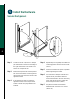
Install the Hardware Rack-Mount the Router (Optional) 53423 Bracket M4 x 10-mm long Phillips flat-head screws (to attach ears to chassis) 4 To rack-mount a Cisco 7507 router, perform the following steps: Step 1 Mount the brackets to the rack posts. Step 2 Secure the spanner bars. Step 3 Attach the chassis ears. Step 4 Mount the chassis.
Install the Hardware Mount Brackets to the Rack Posts Rack post Flange ide ds lde 53382 ie Sh 5 Note The distance between the inner edges of the left and right rack-mounting posts must be at least 17.72 inches (45.088 cm), and the distance between the holes in the mounting posts must be 18.31 inches (46.5 cm) (+ .063 inches or .16 cm). Step 1 Step 2 Step 3 Place the bracket on the inner side of the rack post, with the flanged front edge of the bracket in front of the rack post.
Install the Hardware Secure the Spacers A C 53380 B 6 Step 1 Loosen the 10-32 x 5/8-inch LG Phillips pan-head screw at the end of the ledge of the right-side bracket. This screw is the anchor for the spanner bar. Step 2 Remove the tape that secures the spanner bar on the left bracket, and swing the bar down (see A) over the anchor screw on the opposite bracket. Step 3 If the spanner bar does not reach the opposite bracket, loosen the pan-head screws to allow more play between the brackets.
Install the Hardware Attach the Chassis Ears Center-mount position Flush-mount position H2297 OR Step 1 Position the ears on the chassis as follows: • To flush-mount the chassis, place each ear so that the mounting strips are flush with the end of the chassis, and align the mounting holes in the ear with those in the chassis. • To center-mount the chassis, place each ear with the mounting strips away from the end of the chassis, and align the mounting holes in the ear with those in the chassis.
Install the Hardware Mount the Chassis in the Rack H2298 8 Warning Two people are required to perform this step. Step 1 Slowly lift the chassis in unison. Lower it until it rests on the two ledges of the brackets. Step 2 Slide the chassis back into the rack along the ledges. Step 3 To remove a chassis foot, use a 1/4-inch flat-blade screwdriver or insert a 7/16-inch open-end wrench between the underside of the chassis and the foot.
Install the Hardware Remove the Chassis Foot Chassis foot removal 7/16" nut Flat-blade screwdriver slot for removing chassis foot Step 4 Turn the foot counterclockwise to loosen it until the foot drops out of the chassis. Step 5 Continue sliding the chassis into the rack until the ears meet the front mounting posts on both sides of the rack. Chassis foot Step 6 H1396a Underside of chassis Secure each ear to the rack-mounting post with two 10-32 x 5/8-inch LG Phillips pan-head screws.
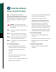
Install the Hardware Install Interface Processors, Fillers, VIPs, or RSPs Card carrier guide (black) A The Route Switch Processor (RSP) comes uninstalled with your Cisco 7507 router, but is a required system component. Install the RSPs in the slot 2 or slot 3, and install any interface processors, fillers, or Versatile Interface Processors (VIPs) in slots 0, 1, 4, 5, and 6 (optional).
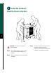
Install the Hardware Install Power Supplies in the Router separate available power sources, connect each power supply to separate input lines—the second power source will likely be available during a failure. Step 1 DC IL FA AC WER PO tive allation ew For DC-input power supplies, turn off the circuit breaker to which you will connect power, and tape the breaker switch to the off position. I 0 This procedure applies to AC-input and DC-input power supplies, with differences clearly noted.
Step 5 Use a screwdriver to tighten the captive installation screw on the top of the power supply. Note For DC-input power supplies, refer to the “Install the DC-Input Power Supply” section on page 13 to complete this procedure. 12 Step 6 Push the cable retention clip away from the power supply receptacle, and push the power cable in until the cable retention clip snaps into place. Step 7 Connect the opposite end of the power cable to an appropriate power source.
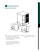
Install the Hardware Install the DC-Input Power Supply Captive installation screws on terminal block cover DO NOT SHIP WITH POWER SUPPLY INSTALLED R TO BE FULLY ENGAGED OPERATING POWER SUPPLY FASTENER TO BE FULLY ENGAGED BEFORE OPERATING POWER SUPPLY 13 OU INP TF UT AIL PO WE R INPUT VOLTAGE : 40-72 V= INPUT CURRENT : 24-13A I allation screws l block cover O B NO SERVICEABLE COMPONENTS INSIDE
Note Perform Step 1 through Step 5 on the previous page before following the steps below. Step 1 Using a screwdriver, loosen the captive installation screws on the terminal block cover. Step 2 Step 3 Lift and remove the terminal block cover. Wire the DC power supply using the appropriate lugs at the wiring end. Note The proper wiring sequence is ground to ground, positive to positive (line to L), and negative to negative (neutral to N).
Connect the RSP The auxiliary port on the RSP is an ETA/TIA DTE DB-25 plug to which you can attach external equipment in order to access the router from the network. The port is located next to the console port on the RSP and is labeled AUX. DB-25 female terminal DB-25 male RSP Step 1 Connect the cable from the auxiliary device to the auxiliary port on the RSP. Step 2 Check your terminal’s documentation to determine the baud rate of the terminal.
Connect the RSP Connect the Console and the Auxiliary Y-Cables AUXILIARY H9720 CONSOLE 16 Auxiliary to auxili RSPs in external y equipment DB-25 The console and auxiliary Y-cables allow you to simultaneously connect the console or auxiliary ports on two RSP2s, RSP4s, or RSP8s, to a single console terminal, or external auxiliary device. These are configured as system master and slave in slots 2 and 3 in the Cisco 7507.
Start and Configure the System Step 1 Check the following components to make sure they are secure: • Each interface processor is inserted all the way into its slot, and captive installation screws are tightened. • All interface cable connections are secured, and any Flash memory cards are secured in their PC slots. • The system power cable is connected. • Check the console terminal to make sure it is connected to the console port and turned on.
Start and Configure the System Start a Basic Configuration Step 7 Many privileged-level EXEC commands are used to set operating parameters.
Start and Configure the System Perform a Basic Configuration Using Setup Note The router’s serial (WAN) cable should not be connected to the CSU/DSU unless you are planning to use AutoInstall. If you are using the console Y-cable that shipped with your router, use either of the two DB-25 male plug ends of the Y-cable. Step 1 Select the protocols supported on your interfaces. For Internet Protocol (IP)-only installations, accept the default values.
Step 7 Enter yes or press Return to configure IP, and then select an interior routing protocol for IP, if you are using IP routing: Configure IP? [yes]: yes Configure IGRP routing? [yes]: yes Your IGRP autonomous system number [1]: 15 Step 8 At the # prompt, enter the copy running-config startup-config command to save the configuration to NVRAM as follows: Hostname# copy running-config startup-config Note Consult your network administrator to obtain network addresses and subnet mask information.
Start and Configure the System Configure an Ethernet Interface Step 1 To configure your system for an Ethernet LAN, respond to the prompts as follows, using your own IP address and subnet mask information: cable range number.
Step 4 At the # prompt, enter the copy running-config startup-config command to save the configuration to NVRAM as follows: Hostname# copy running-config startup-config Your Cisco 7507 router is now minimally configured and ready to use. If you want to modify the parameters after the initial configuration, use the setup command. To perform more complex configurations, use the configure command.
Start and Configure the System Perform a Basic Configuration Using Configuration Mode At the reboot, the following example appears: Any interface listed with OK? value "NO" does not have a valid configuration.
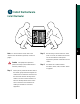
Install Field Replaceable Units (FRUs) Flash Memory Cards NO RM AL A SL SL OT OT 0 1 M AV AST ER E SL NO RM AL B 24 SL SL OT OT 0 1 M AV AST ER E SL NO RM AL C SL SL OT OT 0 1 M AV AST ER E 57002 SL A Flash memory card that ships with your Cisco 7507 contains the Cisco IOS software image to boot your router. You do not need to format it.
The RSP has two PC Card slots—slot 0 and slot 1—into which you can install a Flash memory card. In the RSP2, RSP4, and RSP8, the orientation is vertical. PC Card slot 0 is on the left and slot 1 is on the right (as shown). Note A Flash memory card can be inserted and removed with the system power on. Both PC Card slots can be used at the same time. Step 1 To eject the card, press the appropriate eject button until the card is free of the connector at the back of the slot (see C).
Install Field Replaceable Units (FRUs) Format a Flash Memory Card Flash memory cards shipped as spare parts must be formatted. Use only Intel Series 2+ Flash memory cards. An example of the copy tftp:filename command follows for a file in the Flash memory card in PC Card slot 0: Step 1 Router# copy tftp:myfile1 slot0:myfile1 Enter format slot0: (or format slot1:) to format the Flash memory card, as follows: Router# format slot0: Step 2 At the erase all sectors prompt, press Enter to proceed.
Install Field Replaceable Units (FRUs) Make a Flash Memory Card Image Bootable Note In this example, the filename is new.image, and the Flash memory card is located in slot 0. Step 1 Enter the configure terminal command at the enable prompt, as follows: Router# configure terminal Step 2 Enter the no boot system command, as follows. Router(config)# no boot system Step 3 Enter the boot system flash slot0:new.image command, as follows: Router(config)# boot system flash slot0:new.
Install Field Replaceable Units (FRUs) Prepare to Remove and Install an RSP To remove and install an RSP, you will perform the following steps: 28 • Copy the configuration file using a Trivial File Transfer Protocol (TFTP) server • Remove the RSP • Install the RSP • Connect to the RSP • Turn the system power back on, if it has been turned off • Retrieve the configuration file • Configure high system availability (HSA) or high availability (HA) features, provided you are using two RSPs (Follow
Install Field Replaceable Units (FRUs) Remove and Install an Interface Processor, Filler, VIP, or RSP Note Do not shut down the system power when removing an interface processor, VIP, or an RSP in a system configured for high availability HA. If you are removing an RSP and have only one RSP, shut down the system, but first copy the configuration file to a TFTP server. See the “Copy the Configuration File for an RSP” section on page 32.
Install Field Replaceable Units (FRUs) Step 8 Step 9 If you have a VIP4 and are using HSA with an RSP2 as the slave processor, wait 20-30 seconds, then reinsert the RSP2. Note Boot time is approximately 1 minute for Repeat Step 2 through Step 8 to remove any additional interface processors, fillers, VIPs, or RSPs. Step 4 Verify that all the enabled LEDs (on the interface processors) are on.
Install Field Replaceable Units (FRUs) Check the Interface Processor or VIP Installation Note When a new VIP is inserted or when a VIP is • moved to a new slot, the system recognizes the new interfaces, but leaves them in the shutdown state until you configure them. After the system reinitializes all interfaces, the enabled LED on the port adapters and on all interface processors, VIPs, and RSPs should go on, depending on your connections and configuration.
Install Field Replaceable Units (FRUs) Copy the Configuration File for an RSP Refer to the appropriate Cisco IOS software documentation for the configuration options available, and for specific configuration instructions, as needed. Before you copy (save) the running configuration to a TFTP file server, ensure the following: • You have a connection to the router either with a console terminal connected to the RSP console port or remotely through a Telnet session.
Step 6 Enter the name or IP address of the remote host. In the following example, the name of the remote server is servername: Router# copy startup-config tftp Remote host []? servername Translating "servername"...domain server (1.1.1.
Install Field Replaceable Units (FRUs) Step 7 Enter the name of the configuration file. The default is to use the name of the router with the suffix -confg. Press Return to accept the default filename, or enter a different name for the file, then press Return. In the following example, the default is accepted: Name of configuration file to write [Router-confg]? Write file Router-confg on host 1.1.1.1? [confirm] Writing Router-confg .....
Install Field Replaceable Units (FRUs) Retrieve the Configuration File for RSPs Retrieve the saved configuration and copy it to NVRAM by accessing the router through a console terminal, or from a remote terminal. Step 1 Enter the enable command at the EXEC prompt (>), and then enter a privileged-level password, as follows: Router> enable Password: Router# Note The router runs from the default configuration in NVRAM until the previous configuration is retrieved.
Install Field Replaceable Units (FRUs) The console display indicates whether or not the operation was successful. A series of exclamation points (!!!!) and [OK] (as shown in the preceding example) indicates that the operation was successful. A series of periods (. . .) and [timed out] or [failed] indicates a failure due to a network fault or an incorrect server name, address, or filename). The following is an example of a failed attempt to boot from a remote server: Booting Router-confg .....
Install Field Replaceable Units (FRUs) Remove and Install Port Adapters 37 A Screw B Carrier Lower edge Upper edge
Note First remove the VIP from the chassis before removing the port adapter from the VIP. See the “Remove and Install an Interface Processor, Filler, VIP, or RSP” section on page 29 for instructions. 38 Step 1 Remove the screw that secures the port adapter (or blank port adapter), as shown in A. Step 2 Grasp the handle and carefully pull it out of its slot, away from the edge connector at the rear of the slot. (See A.
Install Field Replaceable Units (FRUs) Remove and Replace the Power Supply Redundant power supplies support online insertion and removal (OIR); if you remove one power supply, the second power supply immediately ramps up to maintain uninterrupted operation. In this case, proceed to Step 2. If you have only one power supply, you must turn off power before removing and replacing it. In this case, proceed to Step 1. Step 1 Turn off the power source. Step 2 Turn off the switch on the power supply.
Install Field Replaceable Units (FRUs) For the DC-input power supply: Use a screwdriver to loosen the captive installation screws on the terminal block cover, lift the cover, use the wire cutters to cut the nylon strain-relief ties, and then remove the three power leads (remove the ground lead last) from the terminal block. See below.
Corporate Headquarters Cisco Systems, Inc. 170 West Tasman Drive San Jose, CA 95134-1706 USA http://www.cisco.com Tel: 408 526-4000 800 553-NETS (6387) Fax: 408 526-4100 European Headquarters Cisco Systems Europe 11, Rue Camille Desmoulins 92782 Issy Les Moulineaux Cedex 9 France http://www-europe.cisco.com Tel: 33 1 58 04 60 00 Fax: 33 1 58 04 61 00 Americas Headquarters Cisco Systems, Inc. 170 West Tasman Drive San Jose, CA 95134-1706 USA http://www.cisco.
42