
Network Router User Manual

3-8
Cisco 7401ASR Installation and Configuration Guide
OL-5419-01 B0
Chapter 3 Starting and Configuring
Functional Overview
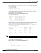
+2.50 V measured at +2.47 V
+3.30 V measured at +3.28 V
+5.00 V measured at +4.98 V
+5.20 V measured at +5.18 V
+12.25 V measured at +12.36 V
-12.00 V measured at -12.15 V
Fans:
Fan 1 is believed to be working
Fan 2 is believed to be working
Fan 3 is believed to be working
Fan 4 is believed to be working
Fan 5 is believed to be working
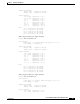
With dual 48V DC power supplies installed:
Router# show environment all
Power Supplies:
Power supply 1 is Redundant 48VDC Power Supply. Unit is on.
Power supply 2 is empty.
Temperature readings:
chassis inlet measured at 34C/93F
chassis outlet measured at 28C/82F
Voltage readings:
+1.8 V (PXF) measured at +1.79 V
+1.8 V (CPU) measured at +1.77 V
+2.50 V measured at +2.47 V
+3.30 V measured at +3.28 V
+5.00 V measured at +4.98 V
+5.20 V measured at +5.18 V
+12.25 V measured at +12.26 V
-12.00 V measured at -12.15 V
Fans:
Fan 1 is believed to be working
Fan 2 is believed to be working
Fan 3 is believed to be working
Fan 4 is believed to be working
Fan 5 is believed to be working
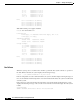
Fan Failures
When the system power is on, all five fans should be operational. The system continues to operate if a
fan fails. When a fan fails, the system displays the following message:
router: 00:03:46:%ENVM-3-BLOWER:Fan 2 may have failed
If the air temperature exceeds a defined threshold, the system controller displays warning messages on
the console terminal, and if the temperature exceeds the shutdown threshold, the system controller shuts
down the system.
If the system does shut down because the temperature exceeded the shutdown threshold, the system
displays the following message on the console screen and in the environment display when the system
restarts:
Queued messages:
%ENVM-1-SHUTDOWN: Environmental Monitor initiated shutdown