Quick Start Guide Cisco 7401ASR Router 1 Documentation and Resources 2 Prepare for Installation 3 Install the Parts 4 Rack-Mount the Router 5 Connect the Router to the Network 6 Connect Power to the Router 7 Configure the Router 8 Obtain Technical Assistance
1 Documentation and Resources This section contains information to help you prepare for installing the Cisco 7401ASR router. It contains a list of online documentation and resources. Documentation Survey Is Cisco documentation helpful? Click here or go to http://forums.cisco.com/eforum/servlet/viewsflash?cmd=showform&pollid=rtgdoc01!rtgdoc to give us your feedback.
All users can order monthly or quarterly subscriptions through the online Subscription Store: http://www.cisco.com/go/subscription Ordering Documentation You can find instructions for ordering documentation at this URL: http://www.cisco.com/univercd/cc/td/doc/es_inpck/pdi.htm You can order Cisco documentation in these ways: • Registered Cisco.com users (Cisco direct customers) can order Cisco product documentation from the Networking Products MarketPlace: http://www.cisco.com/en/US/partner/ordering/index.
2 Prepare for Installation This section contains information about tools and parts, warnings, site preparation information, and information for workbench or tabletop installation and rack-mount installation. Warning Only trained and qualified personnel should install, replace, or service this equipment. Warning Read the installation instructions before you connect the system to its power source. Warning This unit is intended for installation in restricted access areas.
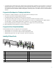
• T1 channel service unit/data service unit (CSU/DSU) that converts the High-Level Data Link Control (HDLC) synchronous serial data stream into a T1 data stream with the correct framing and ones density to connect a serial port to a T1 network. (Some telephone systems require a minimum number of 1 bits per time unit in a data stream, called ones density.) Several T1 CSU/DSU devices are available as additional equipment, and most provide a V.35, EIA/TIA-449, or EIA-530 electrical interface.
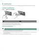
3 Install the Parts This section provides installation instructions for the CompactFlash Disk, Gigabit Interface Converter, and port adapter. Install the CompactFlash Disk Figure 1 Inserting the CompactFlash Disk 2 57604 1 1 Insert the CompactFlash Disk 2 Remove the CompactFlash Disk Insert the CompactFlash Disk into the CompactFlash Disk slot (1) with the label with the vendor name and memory size facing up. The CompactFlash Disk protrudes when completely inserted.
Install the Gigabit Interface Converter Warning Because invisible laser radiation may be emitted from the aperture of the port when no fiber cable is connected, avoid exposure to laser radiation and do not stare into open apertures. Warning Class 1 laser product. Warning Class 1 LED product. • Only two of the four Gigabit Ethernet or Fast Ethernet/Ethernet ports may be used at the same time. • GBIC port 0, FE port 0, and the port adapter are on PCI bus 0. GBIC port 1 and FE port 1 are on PCI bus 1.
Replace the SDRAM DIMM The SDRAM DIMM comes installed with your Cisco 7401ASR router. To replace the SDRAM, follow these instructions: Warning Only trained and qualified personnel should be allowed to install, replace, or service this equipment. Warning Before working on a chassis or working near power supplies, unplug the power cord on AC units; disconnect the power at the circuit breaker on DC units.
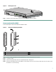
Figure 4 Removing the Cover D LE AB S IER LL R RM CE CAR LA RX RX RX A TX RX ENHANCED ATM 66449 EN Step 7 Slide the cover forward about one-half inch and then lift it from the chassis. Remove and Install the DIMM Follow these steps to remove and install the SDRAM DIMM. Figure 5 Removing and Replacing the DIMM 3 66284 2 1 1 Latch on DIMM socket 2 DIMM 3 Notch Step 1 Attach an ESD-preventative wrist strap between you and an unpainted router surface. Step 2 Locate the DIMM.
Forcing the DIMM, into the socket can damage the DIMM. Use the notches on the DIMM to align the DIMM in the DIMM socket before inserting it. Caution Step 5 Locate the notches and align the DIMM with the socket before inserting it. Step 6 Gently insert the new DIMM, taking care not to damage the pins on the edge of the DIMM. Step 7 Press the spring latches to lock the DIMM in place.
Step 1 Use an ESD wrist strap to ground yourself to the router. A banana jack ground is to the left of the power switch. Step 2 To remove a port adapter, use a Phillips screwdriver to turn the screw holding the port adapter latch. The screw should be loose enough to allow the latch to rotate to an unlocked position (1). The latch can rotate 360o. Step 3 Grasp the handle and pull the port adapter (2) from the router, about halfway out of its slot.
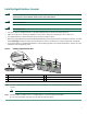
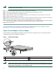
4 Rack-Mount the Router This section provides information for rack-mounting the router. Attach the Rack-Mount Brackets—Chassis Front-Mounted Figure 7 Attaching the Rack-Mount Brackets to the Front of the Chassis D LE AB S IER LL R RM CE CAR LA RX RX RX A TX RX ENHANCED ATM 50531 EN 1 1 Rack-mount bracket 2 2 4 screws, 8-18 x .37 in., for use with a 19-inch rack 4 screws, 8 x .375 in.
Attach the Rack-Mount Brackets—Chassis Rear-Mounted Figure 8 Attaching the Rack-Mount Brackets to the Rear of the Chassis 2 D S IER LL R RM CE CAR LA RX RX RX A TX RX ENHANCED ATM 1 1 Rack-mount bracket 2 50532 LE AB EN 4 screws, 8-18 x .37 in., for use with a 19-inch rack 4 screws, 8 x .375 in., for use in a 21–23-inch rack Depending on how the rack-mount brackets are attached to the chassis, it either protrudes from the rack or is recessed in the rack.
Attach the Cable-Management Bracket Figure 9 Attaching the Cable-Management Bracket 1 D LE AB S IER LL R RM CE CAR LA RX RX RX A TX RX 57578 EN 2 1 Cable-management bracket 2 M4 x 20-mm screw Step 1 Align the cable-management bracket (1) to the rack-mount bracket on the left side of the Cisco 7401ASR router. Step 2 Using a Phillips screwdriver and the M4 x 20-mm screw (2), thread and tighten the screw to the cable-management bracket.
Four-Post Rack Installation Figure 10 Installing the Cisco 7401ASR Router in a Four-Post Rack 1 D LE AB EN S IER LL R RM CE CAR LA RX RX RX A TX RX ENHANCED ATM 2 50534 3 1 Four-post rack 2 Screw hole for cable-management bracket Note 3 Four 12-24 x 0.5-inch screws Inner clearance (the width between the inner sides of the two posts or rails) must be at least 17.3 inches (43.9 cm) The height of the chassis is 1.72 inches (4.37 cm). Airflow through the chassis is from front to back.
Two-Post Rack Installation Figure 11 Installing the Cisco 7401ASR Router in a Two-Post or Telco Rack 1 D R LS RIE M CEL CAR AR RX RX RX AL TX RX ENHANCED ATM 2 1 Two-post or telco-type rack 2 Screw hole for cable-management bracket 57572 LE AB EN 3 3 Four 12-24 x 0.5-inch screws Note Inner clearance (the width between the inner sides of the two posts or rails), must be at least 17.3 inches (43.9 cm) The height of the chassis is 1.72 inches (4.37 cm).
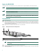
Chassis Ground Connection Installation Figure 12 Attaching the Grounding Lug and Wire to the Chassis 3 2 50536 4 1 1 Chassis ground connector 3 Screws 2 Grounding lug 4 Wire Note The grounding lug and Phillips screws are not available from Cisco Systems. Get the grounding lug from an electrical-connector vendor and the screws from a hardware vendor. See Page 4 for the parts needed. Step 1 Locate the chassis ground connector (1) on the rear of your router chassis.
5 Connect the Router to the Network This section provides information about cables and ports and attaching the router to the network.
For more information, see the online Cisco 7401ASR Installation and Configuration Guide.
Both native Fast Ethernet/Ethernet ports and Gigabit Ethernet ports are reported as GE0/0 and GE0/1 in software. You must use the media-type command to select which media type you want to use before you configure these ports. See “Configure the Native Gigabit Ethernet and Fast Ethernet/Ethernet Interfaces” section on page 28. Note GBIC Cabling and Connection Equipment The Gigabit Interface Converter (GBIC) port is a 1000-Mbps optical interface in the form of an SC-type duplex port that supports IEEE 802.
Attach the appropriate optical fiber cable directly to the SC-type port on the GBIC. You can use either simplex or duplex connectors for most devices. Step 2 Two cables are required for simplex connectors, one cable for transmit (TX) and one for receive (RX). One cable that has both TX and RX connectors is required for duplex connectors. If you plan to use a GBIC-LX/LH at distances greater than 984.25 feet (300 meters) over 50/125-micron or 62.
Port Adapter Cable Connections The instructions for connecting the cables for each port adapter installed in the Cisco 7401ASR router are in the respective online note for each port adapter. The documents are available on the Documentation CD-ROM and on Cisco.com at http://www.cisco.com/univercd/cc/td/doc/product/core/7200vx/portadpt/index.htm. Also see the release notes for any information about a specific port adapter. Release notes are found at http://www.cisco.
6 Connect Power to the Router This section provides instructions for attaching the power cables to the router and powering on the router. Warning This unit might have more than one power cord. To reduce the risk of electric shock, disconnect the two power supply cords before servicing the unit. Warning The AC power supply has double pole/neutral fusing. The Cisco 7401ASR router comes with either an AC or DC power supply. A dual DC power supply option is available.
Step 2 Ensure that no current is flowing through the DC power supply leads. To ensure that all power is OFF, locate the circuit breaker on the panel board that services the DC circuit, switch the circuit breaker to the OFF position, and tape the switch handle of the circuit breaker in the OFF position. Step 3 Using a wire stripper, strip approximately 0.55 inch (14 mm) from the –V and +V leads.
Start the Router Step 1 Place the power switch in the on (|) position. Step 2 Listen for the fans; they should be operating as soon as power is turned on. Note After powering off the router, wait at least 30 seconds before powering it on again. The following table provides information about the LEDs as the system starts. Figure 22 Identifying LEDs and LED Status 2 5 3 6 4 7 57605 1 9 10 8 No.
7 Configure the Router Perform a Basic Configuration Using the Setup Facility If you do not plan to use AutoInstall, do not connect the router’s serial (WAN) cable to the channel service unit/data service unit (CSU/DSU). If the WAN cable is not connected, the router boots from Flash memory and goes automatically into the setup facility. You can run the setup facility any time you are at the enable prompt (#) by entering the setup command.
Note The first two sections of the configuration script (the banner and the installed hardware) appear only at initial system startup. On subsequent uses of the setup command facility, the script begins with a System Configuration Dialog as shown in the following example. --- System Configuration Dialog --At any point you may enter a question mark '?' for help. Use ctrl-c to abort configuration dialog at any prompt. Default settings are in square brackets '[]'.
Step 7 For the following queries, enable routing on AppleTalk and IPX: Configure AppleTalk? [no]: yes Multizone networks? [no]: yes Configure IPX? [no]: yes Step 8 In most cases you use IP routing. If you are using IP routing, you must also select an interior routing protocol. You can specify only one of two interior routing protocols to operate on your system using the setup facility: Interior Gateway Routing Protocol (IGRP) or Routing Information Protocol (RIP).
Step 1 To be able to use a particular media port, use Cisco IOS to select the media type. This is done by using the media-type interface command: media-type { gbic | rj45 } Example: interface GigabitEthernet 0/0 media-type rj45 end Step 2 After changing the media type, configure the speed and duplex to appropriately match the new interface characteristics. Changing the speed and duplex of a Cisco 7401ASR router Gigabit Ethernet interface is done using the speed and duplex interface commands.
Reset the Interface Should you have a problem with your interface and wish to try and reset it, use the command: clear interface GigabitEthernet 0/X (where X is either 0 or 1) Clear Counters Interface counters may be cleared (reset) by using the command: clear counters GigabitEthernet 0/X (where X is either 0 or 1) This will not reset the interface. Configure Port Adapter Interfaces Following are the steps for configuring interfaces to allow communication over a LAN or WAN.
Configure Fast Ethernet Interfaces In the following example, a Fast Ethernet interface in slot X is configured for a Fast Ethernet LAN using IP.
Step 3 If you are using AppleTalk on the interface, enter yes. Enter yes to configure for extended AppleTalk networks, and then enter the cable range number. Enter the zone name and any other additional zones that are associated with your local zone: Configure AppleTalk on this interface? [no]: yes Extended AppleTalk network? [no]: yes AppleTalk starting cable range [0]: Step 4 Save your settings to NVRAM. See the “Save the Running Configuration to NVRAM” section on page 33.
The following configuration command script was created: hostname Router enable secret 5 $1$u8z3$PMYY8em./8sszhzk78p/Y0 enable password betty line vty 0 4 password fred snmp-server community public ! ip routing no vines routing ipx routing appletalk routing no apollo routing no decnet routing no xns routing no clns routing no bridge 1 ! Turn off IPX to prevent network conflicts. interface ATM1/0 ip address 1.1.1.10 255.0.0.1 appletalk cable-range 0-0 0.
Check the Running Configuration Settings To check the value of the settings you have entered, enter the show running-config command at the Router# prompt: Router# show running-config To review changes you make to the configuration, use the EXEC mode show startup-config command to display the information stored in NVRAM.
8 Obtain Technical Assistance Cisco provides Cisco.com, which includes the Cisco Technical Assistance Center (TAC) website, as a starting point for all technical assistance. Customers and partners can obtain online documentation, troubleshooting tips, and sample configurations from the Cisco TAC website. Cisco.com registered users have complete access to the technical support resources on the Cisco TAC website, including TAC tools and utilities. Cisco.com Cisco.
Cisco TAC Escalation Center The Cisco TAC Escalation Center addresses priority level 1 or priority level 2 issues. These classifications are assigned when severe network degradation significantly impacts business operations. When you contact the TAC Escalation Center with a P1 or P2 problem, a Cisco TAC engineer automatically opens a case. To obtain a directory of toll-free Cisco TAC telephone numbers for your country, go to this URL: http://www.cisco.com/warp/public/687/Directory/DirTAC.
Corporate Headquarters Cisco Systems, Inc. 170 West Tasman Drive San Jose, CA 95134-1706 USA www.cisco.com Tel: 408 526-4000 800 553-NETS (6387) Fax: 408 526-4100 European Headquarters Cisco Systems International BV Haarlerbergpark Haarlerbergweg 13-19 1101 CH Amsterdam The Netherlands www-europe.cisco.com Tel: 31 0 20 357 1000 Fax: 31 0 20 357 1100 Americas Headquarters Cisco Systems, Inc. 170 West Tasman Drive San Jose, CA 95134-1706 USA www.cisco.