A P P E N D I X A Using MIBs This chapter describes how to perform tasks on the Cisco 7301 Router.
Appendix A Using MIBs Managing Router Physical Entities • Provides firmware and software information for chassis components The entPhysicalTable enumerates the physical entities contained by the system. In addition, it classifies each physical entity into a vendor type and class. Note The sample outputs and values that appear throughout this chapter are only examples of what you can view when using MIBs.
Appendix A Using MIBs Managing Router Physical Entities Mapping OLD-CISCO-CHASSIS-MIB to ENTITY-MIB Use the ENTITY-MIB instead fo the OLD-CISCO-CHASSIS-MIB on the 7304 platform starting with the following releases: • 12.3T • 12.2SB Serial numbers for the new port adapter hardware has been revised to be alphanumeric values instead of numeric values. As a result, all new hardware might display a zero (0) as cardSerial number in the OLD-CISCO-CHASSIS-MIB, including port adapters.
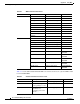
Appendix A Using MIBs Managing Router Physical Entities Table A-1 MIB Containment Information Variables OLD-CISCO-CHASSIS-MIB Equivalent MIB CardIndex entPhysicalIndex ENTITY-MIB CardType entPhysicalVendorType ENTITY-MIB CardDescr entPhysicalDescr ENTITY-MIB CardSerial EntPhysicalSerialNum ENTITY-MIB CardHwVersion entPhysicalHardwareRev ENTITY-MIB CardSwVersion entPhysicalSoftwareRev ENTITY-MIB entPhysicalContainedIn ENTITY-MIB ChassisId entPhysicalSerialNum ENTITY-MIB Chassis
Appendix A Using MIBs Managing Router Physical Entities Performing Inventory Management To obtain information about a particular physical entity in the Cisco 7301 Router walk through the entPhysicalTable in the ENTITY-MIB. The entPhysicalDescr gives a textual description of the entity. Using the entPhysicalIndex that corresponds to the description of the entity, you can obtain other parameters.
Appendix A Using MIBs Managing Router Physical Entities Sample entPhysiclTable Entries The samples in this section show how information is stored the entPhysicalTable. You can determine the router configuration by examining the entPhysicalTable entries. Figure A-1 shows the ENTITY-MIB entPhysicalTable entries for a Gigabit Ethernet line card installed in slot 1 of the router chassis, and for the port on that line card.
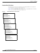
Appendix A Using MIBs Managing Router Physical Entities The following output shows how the information from the MIB walk displays (this is only a section of the complete output): entPhysicalDescr.1 = 7304 Chassis entPhysicalDescr.2 = Chassis Slot entPhysicalDescr.3 = Chassis Slot entPhysicalDescr.4 = Chassis Slot entPhysicalDescr.5 = Chassis Slot entPhysicalDescr.6 = Chassis Slot entPhysicalDescr.7 = Chassis Slot entPhysicalDescr.8 = Power Supply Slot entPhysicalDescr.
Appendix A Using MIBs Managing Router Physical Entities Note The entPhysicalEntry.entPhysicalIndex uniquely identifies each entity in the chassis. Use this index to access information about the entity in other MIB tables. entPhysicalTEntry.1 entPhysicalDescr.1 = 7304 Chassis entPhysicalVendorType.1 = cevChassis7304 entPhysicalContainedIn.1 = 0 entPhysicalClass.1 = chassis(3) entPhysicalParentRelPos.1 = -1 entPhysicalName.1 = 7304 Chassis entPhysicalHardwareRev.1 = E entPhysicalFirmwareRev.
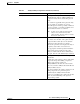
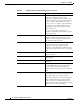
Appendix A Using MIBs Managing Router Physical Entities Table A-3 entPhysicalEntry Configuration Information (continued) entPhysicalTEntries entPhysicalTEntry Description entPhysicalContainedIn = 0 An integer with a range value of 0 through 2147483647. The value of entPhysicalIndex for the physical entity which contains this physical entity. The container is applicable if the physical entity class is capable of containing one or more removable physical entities, possibly of different types.
Appendix A Using MIBs Managing Router Physical Entities Table A-3 entPhysicalEntry Configuration Information (continued) entPhysicalTEntries entPhysicalTEntry Description entPhysicalName = 7304 Chassis The textual name of the physical entity. The value of this object should be the name of the component as assigned by the local device and should be suitable for use in commands entered at the device console.
Appendix A Using MIBs Managing Router Physical Entities Table A-3 entPhysicalEntry Configuration Information (continued) entPhysicalTEntries entPhysicalTEntry Description entPhysicalAssetID = This object is a user-assigned asset tracking identifier for the physical entity as specified by a network manager, and provides non-volatile storage of this information.
Appendix A Using MIBs Managing Router Physical Entities Note Currently, the CISCO-ENTITY-FRU-CONTROL-MIB supports Cisco 7304 line cards. For additional MIB constraints, see the “CISCO-ENTITY-FRU-CONTROL-MIB” section on page 3-21. The following example shows a cefcModuleTable entry for a Cisco 7304 line card whose entPhysicalIndex is 9. cefcModuleEntry.entPhysicalIndex cefcModuleEntry.
Appendix A Using MIBs Managing Router Physical Entities • snmpTargetParamsTable—SNMP parameters to use when generating SNMP notifications. Use the notification enable objects in appropriate MIBs to enable and disable specific SNMP traps. For example, to generate mplsLdpSessionUp or mplsLdpSessionDown traps, the MPLS-LDP-MIB object mplsLdpSessionUpDownTrapEnable must be set to enabled(1).
Appendix A Using MIBs Monitoring Router Interfaces • cefcFRUInserted—An FRU is inserted in the chassis. The trap indicates the entPhysicalIndex of the FRU and the container it was inserted in. • cefcFRURemoved—An FRU is removed from the chassis. The trap indicates the entPhysicalIndex of the FRU and the container it was removed from. Enabling FRU Traps To configure the router to generate traps for FRU events, enter the following command from the CLI.
Appendix A Using MIBs Monitoring Quality of Service Step 3 To enable linkUp and linkDown traps on an interface, set ifLinkUpDownTrapEnable to enabled(1). For information about how to configure the router to send linkDown traps only for the lowest layer of an interface, see the “SNMP Trap Filtering for linkDown Traps” section on page A-15. Step 4 To enable the Internet Engineering Task Force (IETF) standard for linkUp and linkDown traps, issue the following command.
Appendix A Using MIBs Monitoring Quality of Service MIBs Used for QoS CISCO-CLASS-BASED-QOS-MIB Configuring QoS You configure QoS through the command line interface (CLI). For instructions, see the Cisco 7304 Internet Series Router Software Configuration Guide, “Configuring Quality of Service.” Accessing QoS Configuration Information and Statistics The CISCO-CLASS-BASED-QOS-MIB provides access to QoS configuration information and statistics.
Appendix A Using MIBs Monitoring Quality of Service To access QoS configuration information and statistics for a particular QoS feature: 1. Look in cbQosServicePolicyTable and find the cbQosPolicyIndex assigned to the policy in which the feature is used. 2. Use cbQosPolicyIndex to access the cbQosObjectsTable, and find the cbQosObjectsIndex and cbQosConfigIndex assigned to the QoS feature. • Use cbQosConfigIndex to access configuration tables (cbQosxxxCfgTable) for information about the feature.
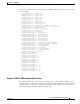
Appendix A Using MIBs Monitoring Quality of Service cbQosObjectsType.9619.9623 = matchStatement(3) cbQosObjectsType.9619.9625 = matchStatement(3) cbQosObjectsType.9619.9627 = queueing(4) cbQosObjectsType.9619.9629 = classmap(2) cbQosObjectsType.9619.9631 = matchStatement(3) cbQosParentObjectsIndex.9583.9583 = 0 cbQosParentObjectsIndex.9583.9585 = 9583 cbQosParentObjectsIndex.9583.9587 = 9585 cbQosParentObjectsIndex.9583.9589 = 9585 cbQosParentObjectsIndex.9583.9591 = 9583 cbQosParentObjectsIndex.9583.
Appendix A Using MIBs Monitoring Quality of Service Note the following about the sample QoS configuration: • Policy maps that are not attached to an interface are not included with SNMP data or displayed by the show policy-map interface command. This is why pm-1Meg is shown but pm1 is not. • The default class map is always included with the SNMP data. • Class maps that have no action defined are not included with the SNMP data.
Appendix A Using MIBs Monitoring Quality of Service Table A-4 QoS Statistics Tables QoS Table Statistics cbQosCMStatsTable Class Map—Counts of packets, bytes, and bit rate before and after QoS policies are executed. Counts of dropped packets and bytes. cbQosMatchStmtStatsTable Match Statement—Counts of packets, bytes, and bit rate before executing QoS policies. cbQosPoliceStatsTable Police Action—Counts of packets, bytes, and bit rate that conforms to, exceeds, and violates police actions.
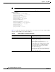
Appendix A Using MIBs Monitoring Quality of Service class-map prec1 match ip prec 1 policy-map car class prec1 police 20000000 24000 24000 conform-action set-dscp-transmit 5 exce ed-action drop class dscp16 police 20000000 24000 24000 conform-action transmit exceed-action transmit interface atm3/0 pvc 1/99 service-policy input car class-map prec2 match ip prec 2 class-map prec1 match ip prec 1 policy-map cbwfq class prec1 bandwidth perc 40 queue-limit 33 class prec2 bandwidth perc 50 queue-limit 55 interf
Appendix A Using MIBs Monitoring Quality of Service Sample QoS Applications This section presents examples of sample code showing how to retrieve information from the CISCO-CLASS-BASED-QOS-MIB to use for QoS billing operations. You can use these examples to help you develop billing applications.
Appendix A Using MIBs Monitoring Quality of Service Manage cases in which a customer interface does not have a service policy attached to it. FOR each ifEntry DO IF (!servicePolicyAssociated[ifIndex].transmit) THEN Perform processing for customer interface without a transmit service policy. END-IF IF (!servicePolicyAssociated[ifIndex].receive) THEN Perform processing for customer interface without a receive service policy.
Appendix A Using MIBs Billing Customers for Traffic Retrieve billing information. x = 0; done = FALSE; WHILE (!done) response = snmp-getnext ( ifIndex = cbQosIfIndex.x, direction = cbQosPolicyDirection.x ); IF (response.status != ‘noError’) THEN done = TRUE ELSE x = extract cbQosPolicyIndex from response; IF (direction == ‘output’) THEN billing[ifIndex].transmit = GetPostPolicyBytes (x); ELSE billing[ifIndex].
Appendix A Using MIBs Billing Customers for Traffic Input and Output Interface Counts The router maintains information about the number of packets and bytes that are received on an input interface and transmitted on an output interface. When a QoS service policy is attached to an interface, the router applies the rules of the policy to traffic on the interface and increments the packet and bytes counts on the interface.
Appendix A Using MIBs Billing Customers for Traffic Note In the above scenario, the Cisco 7301 Router is used as an interim device (that is, traffic originates elsewhere and is destined for another device). Service Policy Configuration This scenario uses the following policy-map configuration. For information on how to create a policy map, see “Configuring Quality of Service” in the Cisco 7304 Internet Series Router Software Configuration Guide.
Appendix A Using MIBs Billing Customers for Traffic Generating Traffic The following set of ping commands generates traffic: 7304# ping Protocol [ip]: Target IP address: 10.0.0.18 Repeat count [5]: 99 Datagram size [100]: 1400 Timeout in seconds [2]: 1 Extended commands [n]: Sweep range of sizes [n]: Type escape sequence to abort. Sending 100, 1400-byte ICMP Echos to 10.0.0.18, timeout is 1 seconds: .!!.!..!.!..!.!.!..!.!..!.!..!.!.!..!.!..!.!..!.!.!..!.!..!.!..!.!.!.. !.!..!.!..!.!.!..!.!..!.!..!.
Appendix A Using MIBs Using CISCO-AAA-SESSION-MIB Using CISCO-AAA-SESSION-MIB The following object support was added to the CISCO-AAA-SESSION-MIB to improve interface mapping sessions: • casnNasPort—Identifies a particular conceptual row associated with the session identified by casnSessionId. The conceptual row that this object points to represents a port that is used to transport a session.