Clear Channel 6-Port T3 (DS3) Line Card Installation and Configuration Product Numbers: 7300-6T3 Platform Supported: Cisco 7304 Corporate Headquarters Cisco Systems, Inc. 170 West Tasman Drive San Jose, CA 95134-1706 USA http://www.cisco.
THE SPECIFICATIONS AND INFORMATION REGARDING THE PRODUCTS IN THIS MANUAL ARE SUBJECT TO CHANGE WITHOUT NOTICE. ALL STATEMENTS, INFORMATION, AND RECOMMENDATIONS IN THIS MANUAL ARE BELIEVED TO BE ACCURATE BUT ARE PRESENTED WITHOUT WARRANTY OF ANY KIND, EXPRESS OR IMPLIED. USERS MUST TAKE FULL RESPONSIBILITY FOR THEIR APPLICATION OF ANY PRODUCTS.
C O N T E N T S Preface vii Objectives vii Organization vii Related Documentation viii Obtaining Documentation viii Cisco.com viii Documentation CD-ROM ix Ordering Documentation ix Documentation Feedback ix Obtaining Technical Assistance x Cisco.
Contents Software and Hardware Requirements 2-2 75-Ohm In-Line Coaxial Attenuator (Optional) Safety Guidelines 2-2 Safety Warnings 2-2 Warning Definition 2-3 Electrical Equipment Guidelines 2-7 Telephone Wiring Guidelines 2-8 Preventing Electrostatic Discharge Damage CHAPTER 3 Removing and Installing Line Cards Installation Overview Handling Line Cards 2-2 2-8 3-1 3-1 3-2 Online Insertion and Removal Warnings and Cautions 3-2 3-3 Line Card Removal and Installation 3-3 Cisco 7304—Removing and I
Contents Using the show diag Command 4-12 Using the show interfaces Command 4-13 DS3 Alarm and Event Detection 4-14 Using the ping Command to Verify Network Connectivity Using loopback Commands 4-15 Bit Error Rate Testing 4-17 CLI-Controlled OIR 4-15 4-17 Line Card Crash Recovery 4-17 Clear Channel 6-Port T3 (DS3) Line Card Installation and Configuration OL-3449-02 v
Contents Clear Channel 6-Port T3 (DS3) Line Card Installation and Configuration vi OL-3449-02
Preface This preface describes the objectives and organization of this document and explains how to find additional information on related products and services.
Preface Related Documentation Related Documentation Your router and the Cisco IOS software running on it contain extensive features and functionality, which are documented in the following resources: • Cisco IOS software: For configuration information and support, refer to the modular configuration and modular command reference publications in the Cisco IOS software configuration documentation set that corresponds to the software release installed on your Cisco hardware.
Preface Obtaining Documentation International Cisco websites can be accessed from this URL: http://www.cisco.com/public/countries_languages.shtml Documentation CD-ROM Cisco documentation and additional literature are available in a Cisco Documentation CD-ROM package, which may have shipped with your product. The Documentation CD-ROM is updated regularly and may be more current than printed documentation. The CD-ROM package is available as a single unit or through an annual or quarterly subscription.
Preface Obtaining Technical Assistance Obtaining Technical Assistance Cisco provides Cisco.com, which includes the Cisco Technical Assistance Center (TAC) website, as a starting point for all technical assistance. Customers and partners can obtain online documentation, troubleshooting tips, and sample configurations from the Cisco TAC website. Cisco.com registered users have complete access to the technical support resources on the Cisco TAC website, including TAC tools and utilities. Cisco.com Cisco.
Preface Obtaining Additional Publications and Information Cisco TAC Website The Cisco TAC website provides online documents and tools to help troubleshoot and resolve technical issues with Cisco products and technologies. To access the Cisco TAC website, go to this URL: http://www.cisco.com/tac All customers, partners, and resellers who have a valid Cisco service contract have complete access to the technical support resources on the Cisco TAC website.
Preface Obtaining Additional Publications and Information • Packet magazine is the Cisco quarterly publication that provides the latest networking trends, technology breakthroughs, and Cisco products and solutions to help industry professionals get the most from their networking investment. Included are networking deployment and troubleshooting tips, configuration examples, customer case studies, tutorials and training, certification information, and links to numerous in-depth online resources.
1 C H A P T E R Overview This chapter describes the 6T3 line card and contains the following sections: • Line Card Overview, page 1-1 • Features, page 1-2 • Interoperability Guidelines for 6T3 Line Card DSUs, page 1-3 • LEDs, page 1-3 • T3 SMB Cables, page 1-4 • Management Information Base, page 1-7 • Line Card Slot Locations on the Supported Platform, page 1-7 • Identifying Interface Addresses, page 1-9 Line Card Overview The 6T3 line card provides a full-duplex operation at T3 (45 Mbps)
Chapter 1 Overview Features Features The 6T3 line card provides the following features: • Single-wide line card for the Cisco 7304 router • Full-duplex synchronous serial DS3 interface • High-Level Data Link Control (HDLC) data • Integrated data service unit (DSU) functionality • Support for 16- and 32-bit cyclic redundancy checks (CRCs) • Support for Frame Relay, HDLC, and PPP serial encapsulations • Support for DS3 MIB (RFC 1407) • Support for remote and local loopbacks • Six independe
Chapter 1 Overview Interoperability Guidelines for 6T3 Line Card DSUs Interoperability Guidelines for 6T3 Line Card DSUs The 6T3 line card supports several types of integrated data service units (DSUs). Table 1-1 lists the feature compatibilities of 6T3 line card DSUs.
Chapter 1 Overview T3 SMB Cables The following conditions must all be met before the 6T3 line card is enabled: • The 6T3 line card is correctly connected and receiving power. • The Network Services Engine 100 (NSE-100) recognizes the 6T3 line card. • The Cisco IOS image on the NSE-100 is running. If any one of these conditions is not met, or if the initialization fails, the STATUS LED does not go on. Table 1-2 lists 6T3 line card LED colors and indications.
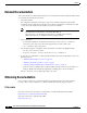
Chapter 1 Overview T3 SMB Cables T3 SMB Cables (SMB Terminates into BNC) 70005 Figure 1-3 SMB connector Note Male BNC connector Female BNC connector Electromagnetic compliance (EMC) was verified with the 10-foot (3.048 meters) shielded cables that are orderable through Cisco. We recommend that you use only the 10-foot (3.048 meters) shielded T3 SMB cables; otherwise, EMC is not guaranteed.
Chapter 1 Overview T3 SMB Cables After you connect the cables to a configured port on the line card, it takes up to 35 seconds to initialize the line card and light the green LNK LED. Ordering Cables You must order cables separately with the 6T3 line card when you order a Cisco 7304 router. Cables are not automatically included with the 6T3 line card. Be sure to specify the type of cable you want shipped with your card (2CBLE-SMB-BNC-M [male] or 2CBLE-SMB-BNC-F [female]).
Chapter 1 Overview Management Information Base Caution Cisco assumes no responsibility for system operation with other than Cisco-supplied adapter cables. The customer is responsible for ensuring that any customer-built cables meet all of the applicable compliance requirements (see the “Related Documentation” section on page viii). T3 systems are designed for cable lengths of 450 feet (137 meters) between the transmitter and the DSX-3 demarcation point where the standard pulse mask must be met.
Chapter 1 Overview Line Card Slot Locations on the Supported Platform Cisco 7304 Router Slot Numbering Figure 1-5 shows a Cisco 7304 with the network services engine (NSE) installed in slots 0 and 1 and line cards installed in slots 2 through 4. In the Cisco 7304, slot 0 is in the lower left position, and slot 5 is in the upper right position.
Chapter 1 Overview Identifying Interface Addresses Identifying Interface Addresses This section describes how to identify interface addresses for the 6T3 line card in the Cisco 7304 router. Interface addresses specify the actual physical location of each interface on a router or switch. Interfaces on the 6T3 line card installed in a router maintain the same address regardless of whether other line cards are installed or removed.
Chapter 1 Overview Identifying Interface Addresses Clear Channel 6-Port T3 (DS3) Line Card Installation and Configuration 1-10 OL-3449-02
C H A P T E R 2 Preparing for Installation This chapter describes the general equipment, safety, and site preparation requirements for installing the 6T3 line card. This chapter contains the following sections: • Required Tools and Equipment, page 2-1 • Software and Hardware Requirements, page 2-2 • 75-Ohm In-Line Coaxial Attenuator (Optional), page 2-2 • Safety Guidelines, page 2-2 Required Tools and Equipment You need the following tools and parts to install a line card.
Chapter 2 Preparing for Installation Software and Hardware Requirements Software and Hardware Requirements Table 2-1 lists the recommended minimum Cisco IOS software release required to use the 6-port 6T3 line card in the 7304 router platform. Table 2-1 6T3 Line Card Software Requirements Router Platform Cisco 7304 Router Recommended Minimum Cisco IOS Release 1 Cisco IOS Release 12.1(10)EX or a later release of Cisco IOS Release 12.1 EX 1.
Chapter 2 Preparing for Installation Safety Guidelines Warning Definition Warning IMPORTANT SAFETY INSTRUCTIONS This warning symbol means danger. You are in a situation that could cause bodily injury. Before you work on any equipment, be aware of the hazards involved with electrical circuitry and be familiar with standard practices for preventing accidents. To see translations of the warnings that appear in this publication, refer to the translated safety warnings that accompanied this device.
Chapter 2 Preparing for Installation Safety Guidelines Attention IMPORTANTES INFORMATIONS DE SÉCURITÉ Ce symbole d'avertissement indique un danger. Vous vous trouvez dans une situation pouvant causer des blessures ou des dommages corporels. Avant de travailler sur un équipement, soyez conscient des dangers posés par les circuits électriques et familiarisez-vous avec les procédures couramment utilisées pour éviter les accidents.
Chapter 2 Preparing for Installation Safety Guidelines Advarsel VIKTIGE SIKKERHETSINSTRUKSJONER Dette varselssymbolet betyr fare. Du befinner deg i en situasjon som kan forårsake personskade. Før du utfører arbeid med utstyret, bør du være oppmerksom på farene som er forbundet med elektriske kretssystemer, og du bør være kjent med vanlig praksis for å unngå ulykker. For å se oversettelser av advarslene i denne publikasjonen, se de oversatte sikkerhetsvarslene som følger med denne enheten.
Chapter 2 Preparing for Installation Safety Guidelines Clear Channel 6-Port T3 (DS3) Line Card Installation and Configuration 2-6 OL-3449-02
Chapter 2 Preparing for Installation Safety Guidelines Electrical Equipment Guidelines Follow these basic guidelines when working with any electrical equipment: • Before beginning any procedure requiring access to the chassis interior, locate the emergency power-off switch for the room in which you are working. • Disconnect all power and external cables before moving a chassis. • Do not work alone when potentially hazardous conditions exist.
Chapter 2 Preparing for Installation Safety Guidelines • Do not perform any action that creates a potential hazard to people or makes the equipment unsafe; carefully examine your work area for possible hazards such as moist floors, ungrounded power extension cables, and missing safety grounds.
C H A P T E R 3 Removing and Installing Line Cards This chapter describes how to remove the 6T3 line card from supported platforms and also how to install a new or replacement line card.
Chapter 3 Removing and Installing Line Cards Handling Line Cards Handling Line Cards Caution Always handle the line card by the carrier edges and handle; never touch the line card components or connector pins. (See Figure 3-1.
Chapter 3 Removing and Installing Line Cards Warnings and Cautions Warnings and Cautions Observe the following warnings and cautions when installing or removing line cards. Caution Do not slide a line card all the way into the slot until you have connected all required cables. Trying to do so disrupts normal operation of the router or switch. Note If a line card lever or other retaining mechanism does not move to the locked position, the line card is not completely seated in the backplane.
Chapter 3 Removing and Installing Line Cards Line Card Removal and Installation Cisco 7304—Removing and Installing a Line Card 1. To remove the line card, loosen the locking thumbscrews on both sides of the line card. 2. Pull out the line card levers and carefully slide the line card halfway out of the slot. If you are removing a blank line card, pull the blank line card completely out of the chassis slot. 3. With the line card halfway out of the slot, disconnect all cables from the line card.
Chapter 3 Removing and Installing Line Cards Connecting a T3 SMB Cable Connecting a T3 SMB Cable On a 6T3 line card, you can use six T3 SMB cables (one for each T3 link). Each T3 link requires separate receive and transmit connections to your external T3 equipment. To connect the T3 SMB cables to the 6T3 line card, follow these steps: Step 1 Attach the T3 SMB cables directly to the SMB ports on the 6T3 line card. Attach the SMB ends of the cable to the ports labeled TX and RX. (See Figure 3-2.
Chapter 3 Removing and Installing Line Cards Connecting a T3 SMB Cable Clear Channel 6-Port T3 (DS3) Line Card Installation and Configuration 3-6 OL-3449-02
C H A P T E R 4 Configuring the 6T3 Line Card To continue your 6T3 line card installation, you must configure the serial interfaces.
Chapter 4 Configuring the 6T3 Line Card Configuring the Interfaces Configuring the Interfaces After you verify that the new 6T3 line card is installed correctly (the STATUS LED goes on), use the privileged-level configure command to configure the new interfaces.
Chapter 4 Configuring the 6T3 Line Card Configuring the Interfaces When you have finished, press Ctrl-Z—hold down the Control key while you press Z—or enter end or exit to exit configuration mode and return to the EXEC command interpreter. Table 4-1 Syntax of the shutdown Command Platform Command Example Cisco 7304 routers interface, followed by the type The example is for interface 0 and interface 1 on a (serial) and slot/port (slot-number/ 6T3 line card in slot 2.
Chapter 4 Configuring the 6T3 Line Card Configuring the Interfaces Step 6 Reenable interfaces by doing the following: a. Repeat Step 3 to reenable an interface. Substitute the no shutdown command for the shutdown command. b. Repeat Step 4 to write the new configuration to memory. Use the copy running-config startup-config command. c. Repeat Step 5 to verify that the interfaces are in the correct state.
Chapter 4 Configuring the 6T3 Line Card Configuring the Interfaces Step 5 Reenable the interfaces using the no shutdown command. (See the “Shutting Down an Interface” section on page 4-2.) Step 6 Configure all additional line card interfaces as required. Step 7 After including all of the configuration subcommands to complete your configuration, press Ctrl-Z—hold down the Control key while you press Z—or enter end or exit to exit configuration mode and return to the EXEC command interpreter prompt.
Chapter 4 Configuring the 6T3 Line Card Configuring the Interfaces Customizing the 6T3 Line Card Configuration There are two sides to the network, a local network side and a remote customer side, or near and far ends. The 6T3 line card supports third-party data service units (DSUs), Internet Service Provider (ISP)-provided DS3 lines, and so on. You can change the configuration parameter default values in the 6T3 line card port interfaces to match the remote DSUs on your network.
Chapter 4 Configuring the 6T3 Line Card Configuring the Interfaces Setting the Sending and Receiving Rate The local and remote DS3 ports must also agree on whether to use a subrate or fullrate sending and receiving rate, because the speed of the sending and receiving rate is regulated by the DSU mode. If the sending and receiving rates do not match, they will not work. Subrates are specific to DSU modes and must be configured appropriately.
Chapter 4 Configuring the 6T3 Line Card Configuring the Interfaces CRC is an error-checking technique that uses a calculated numeric value to detect errors in transmitted data. All interfaces use a 16-bit CRC (CRC-CITT) by default but also support a 32-bit CRC. The sender of a data frame calculates the frame check sequence (FCS). Before it sends a frame, the sender appends the FCS value to the message. The receiver recalculates the FCS and compares its calculation to the FCS from the sender.
Chapter 4 Configuring the 6T3 Line Card Checking the Configuration adtran for connection from a 6T3 line card to an Adtran DSU. Specify digital-link for connection to a Digital Link DSU (DL3100). Specify kentrox for connection from a 6T3 line card to a Kentrox DSU. Specify larscom for connection from a 6T3 line card to a Larscom DSU. Also see the “Interoperability Guidelines for 6T3 Line Card DSUs” section on page 1-3 for information regarding DSU feature compatibilities.
Chapter 4 Configuring the 6T3 Line Card Checking the Configuration Using show Commands to Verify the New Interface Status Table 4-7 demonstrates how you can use the show commands to verify that new interfaces are configured and operating correctly and that the 6T3 line card appears in them correctly. Sample displays of the output of selected show commands appear in the sections that follow.
Chapter 4 Configuring the 6T3 Line Card Checking the Configuration Choose the subsection appropriate for your system. Proceed to the “Using the ping Command to Verify Network Connectivity” section on page 4-15 when you have finished using the show commands.
Chapter 4 Configuring the 6T3 Line Card Checking the Configuration Using the show diag Command Display the types of line cards installed in your system (and specific information about each) using the show diag slot command. Note The outputs that appear in this document may not match the output you receive when running these commands. The outputs in this document are examples only.
Chapter 4 Configuring the 6T3 Line Card Checking the Configuration Using the show interfaces Command The show interfaces command displays status information (including the physical slot and interface address) for the interfaces you specify. The example that follows specifies serial interfaces. Note The outputs that appear in this document may not match the output you receive when running these commands. The outputs in this document are examples only.
Chapter 4 Configuring the 6T3 Line Card Checking the Configuration DS3 Alarm and Event Detection This section assumes that you are familiar with DS3 alarms and line states. The 6T3 line card does not have an LED for alarm and event detection. However, you can enter the show controllers serial slot/port EXEC command to verify whether the alarm and event detection messages are active or inactive.
Chapter 4 Configuring the 6T3 Line Card Checking the Configuration Using the ping Command to Verify Network Connectivity Using the ping command, you can verify that an interface port is functioning properly. This section provides a brief description of this command. Refer to the publications listed in the “Related Documentation” section on page viii for detailed command descriptions and examples. The ping command sends echo request packets out to a remote device at an IP address that you specify.
Chapter 4 Configuring the 6T3 Line Card Checking the Configuration Table 4-8 Using loopback Commands (continued) Command Function Example loopback network payload Sets the interface into network payload loopback mode. Network payload loopback loops just the payload data back toward the network at the T3 framer. Router(config)# interface serial 2/0 Router(config-if)# loopback network payload loopback remote1 Sets the interface into remote loopback mode.
Chapter 4 Configuring the 6T3 Line Card CLI-Controlled OIR Bit Error Rate Testing The ratio of received bits on an interface that contain errors is called the bit error rate (BER). A bit error rate test (BERT) is used to check the BER. T3 bit error rate testing is used on the Cisco 7304 router to check communication between local and remote DS3 ports.
Chapter 4 Configuring the 6T3 Line Card Line Card Crash Recovery The following messages are associated with line card recovery: Error Message 00:00:06:% LC-3-RECOVERY: Line card (slot ) recovery in progress Error Message 00:00:06:% LC-3-EXCESSERRORS: Noof errors seen on the line card (slot ) exceed the threshold When the 6T3 line card encounters any of the non-recoverable errors listed below, the line card is deactivated and must be restarted by performing a CLI-controlled OIR or physically remo