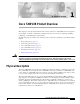
C H A P T E R 1 Cisco 7200 VXR Product Overview This chapter provides physical and functional overviews of the Cisco 7200 VXR routers. Descriptions and examples of software commands are included when they are necessary for replacing, installing, configuring, or maintaining the router hardware.
Chapter 1 Cisco 7200 VXR Product Overview Physical Description The Cisco 7200 VXR routers support the high-speed network processing engine, NPE-G2, and all other available network processing engines. The NPE-G2 provides high-speed performance with the Motorola Freescale 7448 1.67-GHz processor and supports three Gigabit Ethernet interfaces with no additional bandwidth requirements. The NPE-G2 also provides a dedicated Fast Ethernet Management port and two USB ports for data storage and security tokens.
Chapter 1 Cisco 7200 VXR Product Overview Physical Description See Table 1-1 for the Cisco 7200 VXR physical specifications and power requirements: Table 1-1 Physical Specifications Description Specification Midplane Two primary PCI buses, and one secondary PCI bus • With an NPE-G2 or NPE-G1 and an I/O controller installed, the I/O controller does not use bandwidth points, and the NPE-G2 or NPE-G1 does use bandwidth points.
Chapter 1 Cisco 7200 VXR Product Overview Software Requirements Table 1-1 Physical Specifications (continued) Description Specification DC-input current rating 13A at –48 VDC (370W/–48 VDC = 7.7A typical draw) 8A at –60 VDC (370W/–60 VDC = 6.2A typical draw) DC-input cable In accordance with local and national wiring regulations 1. Mbps = megabits per second 2. BTU = British thermal units 3. cfm = cubic feet per minute 4. VAC = volts alternating current 5. A = amperes 6. Hz = hertz 7.
Chapter 1 Cisco 7200 VXR Product Overview Cisco 7204VXR Overview With the NPE-G1 or NPE-G2 installed and the Port Adapter Jacket Card installed in the I/O controller slot, an additional port adapter slot is available. Note If you have difficulty installing a processing engine or I/O controller in the lowest slot of a Cisco 7200 VXR router that is rack-mounted, remove the port adapters, processing engine and I/O controller from the chassis and reinstall them.
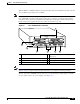
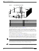
Chapter 1 Cisco 7200 VXR Product Overview Cisco 7204VXR Overview Figure 1-2 Cisco 7204VXR Router—Rear View 3 4 2 5 84396 1 NETWORK PROCESSING ENGINE-300 6 7 8 9 1 Chassis grounding receptacles 6 Network processing engine or network services engine 2 Power supply filler plate 7 AC-input power supply 3 Power switch 8 PWR OK LED 4 AC power cable-retention clip 9 AC power supply receptacle 5 Internal fans The NPE-G2 and NPE-G1 have external connectors and status LEDs for the thr
Chapter 1 Cisco 7200 VXR Product Overview Cisco 7206VXR Overview Three internal fans draw cooling air into the chassis and across internal components to maintain an acceptable operating temperature. (See Figure 1-2.) The three fans are enclosed in a tray that is located inside the chassis.
Chapter 1 Cisco 7200 VXR Product Overview Cisco 7206VXR Overview With the NPE-G1 or NPE-G2 installed and the Port Adapter Jacket Card installed in the I/O controller slot, an additional port adapter slot is available. Note If you have difficulty installing a processing engine or I/O controller in the lowest slot of a Cisco 7200 VXR router that is rack-mounted, remove the port adapters, processing engine and I/O controller from the chassis and reinstall them.
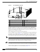
Chapter 1 Cisco 7200 VXR Product Overview Cisco 7206VXR Overview Figure 1-4 Cisco 7206VXR Router—Rear View 3 4 2 5 84396 1 NETWORK PROCESSING ENGINE-300 6 7 8 9 1 Chassis grounding receptacles 6 Network processing engine or network services engine 2 Power supply filler plate 7 AC-input power supply 3 Power switch 8 PWR OK LED 4 AC power cable-retention clip 9 AC power supply receptacle 5 Internal fans The rear of the Cisco 7206VXR router provides access to the network process
Chapter 1 Cisco 7200 VXR Product Overview Field-Replaceable Units Adjacent to the power supply bays are two chassis grounding receptacles that provide a chassis ground connection for ESD equipment or a two-hole grounding lug. (See Figure 1-4.) Three internal fans draw cooling air into the chassis and across the internal components to maintain an acceptable operating temperature. (See Figure 1-4.) The three fans are enclosed in a tray that is located inside the chassis.
Chapter 1 Cisco 7200 VXR Product Overview Field-Replaceable Units Note • CompactFlash Disks, Flash Disks, and PC Cards, page 1-52 • Rack-Mount and Cable-Management Kit, page 1-53 Replacement instructions for removing and replacing FRUs are contained in separate online documents. For example, if you need to replace an AC power supply in your Cisco 7200 VXR router, refer to the 280-Watt AC-Input Power Supply Replacement Instructions publication.
Chapter 1 Cisco 7200 VXR Product Overview Field-Replaceable Units – The NPE-200 has an R5000 microprocessor that operates at an internal clock speed of 200 MHz. – The NPE-175 has an RM5270 microprocessor that operates at an internal clock speed of 200 MHz. – The NPE-100 and NPE-150 have an R4700 microprocessor that operates at an internal clock speed of 150 MHz.
Chapter 1 Cisco 7200 VXR Product Overview Field-Replaceable Units – The NPE-100, NPE-150, and NPE-200 use DRAM for storing routing tables, network accounting applications, packets of information in preparation for process switching, and packet buffering for SRAM overflow (except in the NPE-100, which contains no packet SRAM). The standard configuration is 32 MB, with up to 128 MB available through single in-line memory module (SIMM) upgrades.
Chapter 1 Cisco 7200 VXR Product Overview Field-Replaceable Units • Booting and reloading images • Managing port adapters (recognition and initialization during online insertion and removal) The following figures and memory tables provide information about your NPE or NSE: • NPE-G2 is represented by Figure 1-5. Table 1-3 lists NPE-G2 memory specifications, and Table 1-3 lists memory configurations. • NPE-G1 is represented by Figure 1-6.
Chapter 1 Cisco 7200 VXR Product Overview Field-Replaceable Units Figure 1-5 NPE-G2 1 10 9 2 8 4 3 5 7 149061 6 1 Midplane connectors 6 Flash memory (U13) 2 Boot ROM (U24) 7 DIMM (socket—S1) 3 NVRAM (on bottom of board—U17) 8 Temperature sensor (inlet—U23) 4 Temperature sensor (outlet—U20) 9 Processor (U30) 5 Flash memory (U19) 10 Keying post Table 1-2 lists the NPE-G2 memory specification, and Table 1-3 lists the factory-installed SDRAM configurations and their product numb
Chapter 1 Cisco 7200 VXR Product Overview Field-Replaceable Units Table 1-2 NPE-G2 Memory Specifications (continued) Memory Type Size Quantity Component Location on the NPE-G2 Board Description Primary cache 32 KB (16 KB — instruction, 16 KB data) Motorola Freescale 7448 processor, internal cache U30 Secondary cache 1 MB Motorola Freescale 7448 secondary cache U30 Table 1-3 NPE-G2 SDRAM Configuration—Configurable Memory Only — Total SDRAM SDRAM Bank Quantity 1 GB S1 1-GB DIMM Figur
Chapter 1 Cisco 7200 VXR Product Overview Field-Replaceable Units Table 1-4 NPE-G1 Memory Specifications Component Location on the NPE-G1 Board Memory Type Size Quantity Description SDRAM 128 MB, 256 MB, 512 MB 2 128-MB, 256-MB, or 512-MB SODIMMs J3, J4 Boot ROM 512 KB 1 Reprogrammable Boot ROM for the ROM monitor program U1 Flash Memory 16 MB 1 Contains the default U25 and U26 boot helper (boot loader) image NVRAM 512 KB 1 Nonvolatile EPROM for the system configuration file U7 P
Chapter 1 Cisco 7200 VXR Product Overview Field-Replaceable Units Figure 1-7 NSE-1 1 8 2 10 3 9 11 12 4 NETWORK PROCESSING ENGINE-200 6 5 66418 13 7 1 Network controller board 8 Midplane connectors 2 Keying post 9 Boot ROM (U1) 3 System controller 10 Temperature sensor 4 Processor engine board 11 SDRAM 5 Captive installation screw 12 Parallel eXpress Forwarding engine (PXF processor) 6 RM7000 microprocessor 13 Temperature sensor 7 Handle Table 1-6 lists the NSE-1 memo
Chapter 1 Cisco 7200 VXR Product Overview Field-Replaceable Units Table 1-6 NSE-1 Memory Specifications (continued) Location1 Memory Type Size Quantity Description Secondary cache 256 KB — RM7000 processor, U22 internal, unified instruction and data cache Tertiary cache 2 MB (fixed) — RM7000 processor, external cache U7, U9, U12, U14, U17 1. Location on processing engine board. See Figure 1-7.
Chapter 1 Cisco 7200 VXR Product Overview Field-Replaceable Units Table 1-8 lists the NPE-400 memory specifications, and Table 1-9 lists factory-installed SDRAM configurations and their product numbers.
Chapter 1 Cisco 7200 VXR Product Overview Field-Replaceable Units Figure 1-9 NPE-300 1 2 11 12 13 3 4 14 15 5 NETWORK PROCESSING ENGINE-300 6 7 8 66410 16 9 10 1 Midplane connectors 9 2 Keying post 10 Temperature sensor (U42) 3 DIMM 3 (U44) 11 Keying post 4 Bank 1 (user configurable) 12 Temperature sensor 5 DIMM 2 (U45) 13 Boot ROM (U1) 6 Captive installation screw 14 DIMM 0 (U16) 7 Handle 15 Bank 0 (fixed size) 8 System controllers 16 U15 never populated RM7000 micro
Chapter 1 Cisco 7200 VXR Product Overview Field-Replaceable Units Table 1-10 NPE-300 Memory Specifications (continued) Memory Type Size Quantity Description Location1 Secondary cache 256 KB — RM7000 processor, internal, unified instruction and data cache U49 Tertiary cache 2 MB (fixed) — RM7000 processor, external cache U7, U8, U9, U10, U17 1. Location on processing engine board. See Figure 1-9. 2. Bank 0 is used exclusively for packet memory and is not user configurable. 3.
Chapter 1 Cisco 7200 VXR Product Overview Field-Replaceable Units Figure 1-10 NPE-225 1 7 8 9 2 10 NETWORK PROCESSING ENGINE-200 4 5 66417 3 6 1 Network controller board 6 Handle 2 System controller 7 Midplane connectors 3 Processor engine board 8 Boot ROM (U1) 4 Captive installation screw 9 Temperature sensor 5 RM5271 microprocessor 10 SDRAM DIMM (U15) Table 1-12 lists the NPE-225 memory specifications, and Table 1-13 lists factory-installed SDRAM configurations and their pro
Chapter 1 Cisco 7200 VXR Product Overview Field-Replaceable Units Table 1-12 NPE-225 Memory Specifications Memory Type Size Quantity Description Location1 SDRAM 64, 128, 256 MB 1 SDRAM slot 64-MB, 128- MB, or 256-MB SDRAM DIMM U15 Boot ROM 512 KB — One-time programmable ROM U1 Primary cache 16 KB (instruction), — 16 KB (data) RM527x U4 processor, internal cache 32 KB (instruction), — 32 KB (data) RM527x U4 processor, internal cache 2 MB RM527x processor, unified external cache Sec
Chapter 1 Cisco 7200 VXR Product Overview Field-Replaceable Units Figure 1-11 NPE-200 7 8 9 10 1 U52 11 U42 2 U25 12 3 NETWORK PROCESSING ENGINE-200 4 66420 U11 6 5 1 System controller 7 Midplane connectors 2 R5000 microprocessor 8 Temperature sensor 3 4-MB SRAM (U6, U10, U13, U14, U28, U29, 9 U38, and U39) 4 Captive installation screw 10 DRAM SIMMs 5 Handle 11 Bank 1 6 Temperature sensor 12 Bank 2 Boot ROM (U92) Table 1-14 lists the NPE-200 memory specifications, and Ta
Chapter 1 Cisco 7200 VXR Product Overview Field-Replaceable Units Table 1-14 NPE-200 Memory Specifications (continued) Location1 Memory Type Size Quantity Description Primary cache — — R5000 processor, U44 internal cache Secondary cache 512 KB 4 R5000 processor, U16, U9, U109, unified external and U107 cache 1. Location on processing engine board. See Figure 1-11. 2.
Chapter 1 Cisco 7200 VXR Product Overview Field-Replaceable Units Figure 1-12 NPE-175 1 7 8 9 2 10 NETWORK PROCESSING ENGINE-150 4 5 66416 3 6 1 Network controller board 6 Handle 2 System controller 7 Midplane connectors 3 Processor engine board 8 Boot ROM (U1) 4 Captive installation screw 9 Temperature sensor 5 RM5270 microprocessor 10 SDRAM DIMM (U15) Table 1-16 lists the NPE-175 memory specifications, and Table 1-17 lists memory configurations.
Chapter 1 Cisco 7200 VXR Product Overview Field-Replaceable Units Table 1-16 NPE-175 Memory Specifications Memory Type Size Quantity Description Location1 SDRAM 64 or 128 MB 1 SDRAM slot DIMM U15 Boot ROM 512 KB — One-time programmable ROM U1 Primary cache 16 KB (instruction), 16 KB (data) — RM527x processor, U4 internal cache 32 KB (instruction), 32 KB (data) — RM527x processor, U4 internal cache 2 MB 4 chips, each 512K RM527x processor, U5, U6, U7, U8 by 8 bits wide unified ext
Chapter 1 Cisco 7200 VXR Product Overview Field-Replaceable Units Figure 1-13 NPE-150 7 8 9 1 U12 10 U4 2 U25 11 3 NETWORK PROCESSING ENGINE-150 4 66424 U18 6 5 1 System controller 7 Midplane connectors 2 R4700 microprocessor 8 Temperature sensor 3 1-MB SRAM (U700 through U703, U800 through U803) 9 DRAM SIMMs 4 Captive installation screw 10 Bank 1 5 Handle 11 Bank 0 6 Temperature sensor Table 1-18 lists the NPE-150 memory specifications, and Table 1-19 lists memory confi
Chapter 1 Cisco 7200 VXR Product Overview Field-Replaceable Units Note To prevent DRAM errors in the NPE-100, NPE-150, or NPE-200, and to ensure that your system initializes correctly at startup, DRAM bank 0 (socket U18 and U25, or U11 and U25) must contain no fewer than two SIMMs of the same type. You may also install two SIMMs of the same type in bank 1 (socket U4 and U12, or U42 and U52); however, bank 0 must always contain the two largest size SIMMs.
Chapter 1 Cisco 7200 VXR Product Overview Field-Replaceable Units Table 1-20 NPE-100 Memory Specifications Memory Type Size Quantity Description Location1 DRAM 32 to 128 MB 2 to 4 16- or 32-MB SIMMs (based on maximum DRAM required) Bank 0: U18 and U25 Bank 1: U4 and U12 Boot ROM The NPE-100 uses boot ROM present on the I/O controller. Primary cache — — R4700 processor, internal cache U201 Secondary cache 512 KB 4 R4700 processor, unified, external cache U2, U10, U14, and U26 1.
Chapter 1 Cisco 7200 VXR Product Overview Field-Replaceable Units Input/Output Controller This section describes five different models of I/O controllers. These models are distinguished from one another by their Ethernet interface options. Table 1-22 lists the I/O controllers by product number and describes their differences.
Chapter 1 Cisco 7200 VXR Product Overview Field-Replaceable Units Figure 1-15 C7200-I/O-GE+E—With GBIC Gigabit Ethernet and RJ-45 Ethernet Receptacles 1 3 2 6 4 7 5 1 SL D LE AB T IA EC MC EJ PC OT 0 SL RT RX PO E O G TX K D 1 E L E LIN L E S 1 TD A T L C E N C U S A E D AS Y D O L O D R K V E P IT EC L D VE1 O E M T L T AS C 1 K IT S U S U U LA D S D D O A O O C R L R R E P C P P D K ETHERNET GIGABIT ETHERNET INPUT/OUTPUT CONTROLLER LIN R PW IO K O U CP ET S RE RT 0 PO E E O
Chapter 1 Cisco 7200 VXR Product Overview Field-Replaceable Units 1 3 2 6 4 7 5 1 K K LIN SL DUAL FAST ETHERNET INPUT/OUTPUT CONTROLLER LIN D LE AB T EC IA MC EJ PC OT s 0 SL bp 0 10 M E/E s bp 0 0 F 10 M F E/E 1 R PW IO K O U CP ET S RE E OL X AU NS CO 84525 OT C7200-I/O-2FE/E EN 8 9 11 12 10 1 Temperature sensor 7 SRAM (U19) 2 Midplane connectors 8 Captive installation screw 3 Battery for SRAM 9 PC Card slots 4 8-MB Flash memory (soldered)
Chapter 1 Cisco 7200 VXR Product Overview Field-Replaceable Units Figure 1-17 C7200-I/O-FE—With MII and RJ-45 Fast Ethernet Receptacles (Version 1) 2 3 1 5 4 1 LO S II FE 5 J4 N E M FAST ETHERNET INPUT/OUTPUT CONTROLLER 5 J4 K LIN R T R E S E U R P D C LE B A N E T T C IA JE C M E C P N 0 LO II M S E 5 R W P OK O J4 R LE X U O A S N I/ O C 84531 T 6 7 8 12 9 13 11 10 1 Temperature sensor 8 PC Card slots 2 Midplane connectors 9 Optio
Chapter 1 Cisco 7200 VXR Product Overview Field-Replaceable Units Figure 1-18 C7200-I/O-FE—With MII and RJ-45 Fast Ethernet Receptacles (Version 2) 1 2 3 4 5 7 8 6 1 II FE 5 J4 N E M FAST ETHERNET INPUT/OUTPUT CONTROLLER 5 J4 K LIN R T R E S E U 84523 T LO S R P D C LE B A N E T T C IA C M C P JE E R N 0 II E M LO S 5 J4 R I/O LE X W K O U P O A S N O C 9 10 14 11 15 13 12 1 Temperature sensor 9 2 FPGA configuration PROM (U9) 10
Chapter 1 Cisco 7200 VXR Product Overview Field-Replaceable Units Note In n Figure 1-20, the NVRAM is replaced by an SRAM component (U14) that is made to act like the NVRAM by the addition of some external components, one of which is the button-type lithium battery labeled “Battery for SRAM.
Chapter 1 Cisco 7200 VXR Product Overview Field-Replaceable Units Figure 1-20 C7200-I/O—Without Fast Ethernet Port (Version 2) 1 2 3 4 5 7 8 6 T 1 INPUT/OUTPUT CONTROLLER LO T S E S 84524 E U R P D C LE B A N E T T C IA C M C P JE E R 0 LO S I/O LE X W K O U P O A S N O C 9 10 13 14 12 11 1 Temperature sensor 8 Battery for SRAM 2 FPGA configuration PROM (U9) 9 Captive installation screw 3 Midplane connectors 10 PC Card slots 4 4-MB Flas
Chapter 1 Cisco 7200 VXR Product Overview Field-Replaceable Units Figure 1-21 C7200-I/O-FE-MII—With Single MII Fast Ethernet Receptacle 2 3 1 5 4 1 FAST ETHERNET INPUT/OUTPUT CONTROLLER II LO S FE M D LE B A N E LE T T C IA JE C M E C P N LO E S F E T K B A 0 E LIN F U P C K E S E R R W P O LE X U O A S N O IO C 84534 T 6 7 8 11 9 Note 12 10 1 Temperature sensor 7 Captive installation screw 2 Midplane connectors 8 PC Card slots
Chapter 1 Cisco 7200 VXR Product Overview Field-Replaceable Units Table 1-23 I/O Controller Memory Components Type Boot ROM 1 Flash memory Size Quantity Memory Description Model 256 KB 1 32-pin DIP-type C7200-I/O-FE-MII U20 32-pin DIP-type or 32-pin PLCC-type C7200-I/O-FE, C7200-I/O Contains the default boot helper image C7200-I/O-FE-MII U99 4 MB 1 C7200-I/O-FE, C7200-I/O Location U20 or U4 U99 or U10, U11, U12, and U13 (soldered)2 8 MB 1 Flash memory card 16 or 20 MB Up to 2 F
Chapter 1 Cisco 7200 VXR Product Overview Field-Replaceable Units or not an I/O controller is in the system with the NPE-G1 or NPE-G2. The SLOT ACTIVE LED is on if there is a CompactFlash Disk in the NPE-G1. The CF ACTV LED is on if there is a CompactFlash Disk in the NPE-G2. Caution To prevent system errors and problems, use the CPU reset button only at the direction of your service representative. Table 1-24 lists LEDs common to all models of I/O controllers and describes their functions.
Chapter 1 Cisco 7200 VXR Product Overview Field-Replaceable Units Table 1-25 NPE-G2 LEDs (continued) LED Label LED Color Status in the Power Up State USB USB ports Flashing green Activity Off No activity CompactFlash Disk Flashing green Activity Off No activity System status Solid green Cisco IOS has successfully booted. Flashing yellow ROMmon is loading. Solid yellow ROMmon has successfully booted. Flashing green Cisco IOS is loading. Green The NPE-G2 has powered on.
Chapter 1 Cisco 7200 VXR Product Overview Field-Replaceable Units Input/Output Controller C7200-I/O LEDs Figure 1-22 shows the LEDs on the I/O controller model with no Ethernet ports (C7200-I/O). This I/O controller has no port-specific LEDs. Table 1-24 describes the LEDs on this I/O controller.
Chapter 1 Cisco 7200 VXR Product Overview Field-Replaceable Units C7200-I/O-GE+E LEDs and CPU Reset Button OT C7200-I/O-GE+E 1 SL D LE AB EN IA MC PC T EC OT RT 0 RX POGE 0 SL EJ OT TX K K D 1 E L E LIN L E S 1 TD A T L C E N C U S A E D AS Y D O L O D R K V E P IT EC L D VE1 O E M T L T AS C 1 K IT S U S U U LA D S D D O A O O C R L PRPR E P D C ETHERNET GIGABIT ETHERNET INPUT/OUTPUT CONTROLLER LIN R PW IO K O U CP ET S RE RT 0 PO E E OL X AU NS CO 33446 Figure 1-23 1 S
Chapter 1 Cisco 7200 VXR Product Overview Field-Replaceable Units Table 1-28 C7200-I/O-2FE/E I/O Controller LEDs LED Color Function 100 Mbps Green Indicates that the port is configured for 100-Mbps operation (speed 100), or if configured for autonegotiation (speed auto), the port has detected a valid link at 100 Mbps. Note LINK Green If the port is configured for 10-Mbps operation, or if it is configured for autonegotiation and the port has detected a valid link at 10 Mbps, the LED remains off.
Chapter 1 Cisco 7200 VXR Product Overview Field-Replaceable Units C7200-I/O-FE LEDs and CPU Reset Button T E FAST ETHERNET INPUT/OUTPUT CONTROLLER S 5 E J-4 R U R P D C LE B A N E 5 J4 N E 5 J4 K LIN R R R W P IO OK SL O T 1 II M N E H11294 Figure 1-25 ED T E S BL E A EN 5 J4 R N E 5 J4 R INK L U R P R W P K IO O C SL O T 0 II M N E 1 II FE 5 J4 N E M FAST ETHERNET INPUT/OUTPUT CONTROLLER 5 J4 K LIN R T R E S E U R P C T T C IA JE C M
Chapter 1 Cisco 7200 VXR Product Overview Field-Replaceable Units Note An MII LINK LED is not provided on this I/O controller because the LED is provided on external transceivers that are required for connecting to the MII receptacle on the I/O controller. See Chapter 3, “Installing a Cisco 7200 VXR Router,” the “Connecting to the I/O Controller Ethernet and Fast Ethernet Ports” section on page 3-30 for Fast Ethernet MII connection requirements.
Chapter 1 Cisco 7200 VXR Product Overview Field-Replaceable Units Note The port adapters installed in the Cisco 7200 VXR routers support OIR. For an explanation of OIR, see the “Online Insertion and Removal” section on page 1-57. All port adapters and service adapters connect to two Peripheral Component Interconnect (PCI) buses on the router midplane. The PCI buses provide a path to packet I/O memory and the system (route/switch) processor.
Chapter 1 Cisco 7200 VXR Product Overview Field-Replaceable Units Power Supplies The Cisco 7200 VXR routers come equipped with one 280W AC-input power supply. (A 280W DC-input power supply is available as an option.) You must order the second power supply separately. A second power supply, although not required, allows load sharing and increased system availability. Note The Cisco 7200 VXR power supplies are the same as in all Cisco 7200 series routers.
Chapter 1 Cisco 7200 VXR Product Overview Field-Replaceable Units Figure 1-28 Cisco 7200 Series AC-Input Power Supply 84397 7 1 2 3 4 5 6 1 Captive installation screw 5 AC-input receptacle 2 Power switch guard 6 Handle 3 OK LED 7 Power cable- retention clip 4 Power switch The AC-input power supply has a receptacle for an AC-input power cable. A modular power cable connects the AC-input power supply to the site AC power source.
Chapter 1 Cisco 7200 VXR Product Overview Field-Replaceable Units The DC-input power supply has DC-input power leads that are hardwired to a DC-input terminal block. A cable tie is shipped with each DC-input power supply to secure the leads to the power supply faceplate and provide strain relief for the leads. Caution To ensure adequate airflow across the router power supplies, a power supply or a power supply filler plate must be installed in each power supply bay.
Chapter 1 Cisco 7200 VXR Product Overview Field-Replaceable Units Figure 1-30 Cisco 7200 VXR Chassis—7206VXR Shown 6 5 4 3 14628 0 2 1 Cisco 7200 Series VXR CompactFlash Disks, Flash Disks, and PC Cards The Cisco 7206VXR supports up to two installed Flash Disks or two PC Cards, also called Flash memory cards. The NPE-G1 supports one CompactFlash Disk, as does the NPE-G2.
Chapter 1 Cisco 7200 VXR Product Overview Field-Replaceable Units See Table 1-31, Table 1-32, and Table 1-33 for the factory-installed Flash memory card options and their product numbers, the Flash Disk memory options and their product numbers, and the CompactFlash Disk memory options and their product numbers. Configurations for flash memory cards, flash disks and CompactFlash Disks are in this section.
Chapter 1 Cisco 7200 VXR Product Overview Functional Overview Functional Overview This section provides a functional overview of the Cisco 7200 VXR routers. It describes the numbering and addressing scheme of the port adapters for the router, the environmental monitoring and reporting functions, and online insertion and removal (OIR). These descriptions help you become familiar with the capabilities of the Cisco 7200 VXR routers.
Chapter 1 Cisco 7200 VXR Product Overview Functional Overview Figure 1-32 Port Adapter Slot Numbering—Cisco 7206VXR 1 2 3 4 3 2 1 0 6 TOKEN RING 5 FAST ETHERNET 4 K 0 LIN MII RJ4 5 D 1 ET ES 2 TX RX 4 TX RX 3 TX RX 2 RX TX EN II C 45 LE D 0 R J- PU R M FE T O SL FAST ETHERNET INPUT/OUTPUT CONTROLLER AB O PW K R 84518 R E J4 N 5 M E II N 1O T 0 T EC O SL EJ PC M C IA Cisco 7200 Series VXR EN 7 1 1 0 RX CD LB RC RD TC TD CD LB RC RD T
Chapter 1 Cisco 7200 VXR Product Overview Functional Overview Router# show interfaces FastEthernet0/0 is administratively down, line protocol is down Hardware is i82543 (Livengood), address is 0000.0000.0000 (bia 0000.0000.0000) MTU 1500 bytes, BW 100000 Kbit, DLY 100 usec, reliability 255/255, txload 1/255, rxload 1/255 (display text omitted) FastEthernet0/1 is administratively down, line protocol is down Hardware is i82543 (Livengood), address is 0000.0000.0000 (bia 0000.0000.
Chapter 1 Cisco 7200 VXR Product Overview Functional Overview The following example shows the display for the first port on the Fast Ethernet port adapter in port adapter slot 3: Router# show interface fastethernet 5/0 FastEthernet5/0 is up, line protocol is up Hardware is DEC21140, address is 0000.000.0000 (bia 0000.0000.0000) Internet address is 0.0.0.
Chapter 1 Cisco 7200 VXR Product Overview Functional Overview Note The Port Adapter Jacket Card does not support OIR. However, the port adapter installed in the Port Adapter Jacket Card does support OIR. Note As you disengage the port adapter from the router or switch, online insertion and removal (OIR) administratively shuts down all active interfaces in the port adapter.
Chapter 1 Cisco 7200 VXR Product Overview Functional Overview Environmental Monitoring and Reporting Functions Environmental monitoring and reporting functions are controlled by the network processing engine or network services engine and allow you to maintain normal system operation by identifying and resolving adverse conditions prior to loss of operation. The environmental monitoring functions constantly monitor the internal chassis air temperature and DC supply voltages and currents.
Chapter 1 Cisco 7200 VXR Product Overview Functional Overview Table 1-34 NPE-G2Processor-Monitored Temperature Thresholds NPE-G21 Low Warning High Warning Shutdown NPE inlet 111 F (44 C) 138 F (59 C) 176oF (80oC) NPE outlet 120 F (49 C) 147 F (64 C) 183 F (84 C) I/O controller inlet 105 F (41 C) 132 F (56 C) 168 F (76 C) I/O controller outlet 107 F (42 C) 134 F (57 C) 170 F (77 C) CPU Die 194 F (90 C) 221 F (105 C) 230 F (110 C) 1. With an I/O controller installed.
Chapter 1 Cisco 7200 VXR Product Overview Functional Overview Table 1-37 Note Typical Power Supply-Monitored DC-Voltage Thresholds Parameter Low Critical Low Warning High Warning High Critical +3.45V +3.26V +3.34V +3.55V +3.63V +5.15V +4.86V +4.99V +5.31V +5.43V +12.15V +11.39V +11.67 +12.62V +12.91V –11.95V –9.52V –10.73 –13.16V –14.38V A low warning or high warning message does not mean that the router is at risk of malfunctioning or being damaged.
Chapter 1 Cisco 7200 VXR Product Overview Functional Overview Below are sample high critical messages from chassis with 3V and 5V power supplies in Cisco IOS Release 12.0(23): Router(boot)# 00:02:47:%ENVM-2-ENVCRIT:+3.45 V measured at +3.72 Router(boot)# 00:06:51:%ENVM-2-ENVCRIT:+5.15 V measured at +5.49 Reporting Functions The Cisco 7200 VXR routers display warning messages on the console if chassis interface-monitored parameters exceed a desired threshold.
Chapter 1 Cisco 7200 VXR Product Overview Functional Overview Following is sample output of the show environment last command: NPE300(boot)# show environment last chassis inlet previously measured at 26C/78F chassis outlet 1 previously measured at 28C/82F chassis outlet 2 previously measured at 29C/84F chassis outlet 3 previously measured at 33C/91F +3.45 V previously measured at +3.46 +5.15 V previously measured at +5.23 +12.15 V previously measured at +12.24 -11.95 V previously measured at -11.
Chapter 1 Cisco 7200 VXR Product Overview Functional Overview Following is sample output of the show environment all command: NPE300(boot)# show environment all Power Supplies: Power Supply 1 is empty. Power Supply 2 is Zytek AC Power Supply. Unit is on. Temperature chassis chassis chassis chassis readings: inlet measured outlet 1 measured outlet 2 measured outlet 3 measured Voltage readings: +3.45 V +5.15 V +12.15 V -11.