
Network Router User Manual


B-1
Cisco 3825 Mobile Wireless Edge Router Software Configuration Guide
OL-15667-03
APPENDIX
B
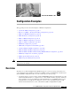
Configuration Examples
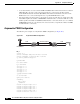
This appendix provides real-world examples of RAN-O configurations.
• Asymmetric PWE3 Configuration, page B-2
• Ethernet over MPLS—VLAN and Port Mode Configuration, page B-15
• PWE3 over MLPPP Configuration, page B-21
• PWE3 Redundancy Configuration, page B-30
• TDM over MPLS Configuration, page B-36
• ATM over MPLS Configurations, page B-41
• ATM over L2TPv3 Configuration, page B-48
• GSM Only Configuration, page B-55
• UMTS Only Configuration without IMA, page B-59
• Combined GSM and UMTS Configuration, page B-63
• GSM and UMTS with IMA Configuration, page B-68
• GSM and UMTS with IMA and PVC Routing (HSDPA Offload) Configuration, page B-74
• GSM Only Configuration via Satellite, page B-80
• GSM Congestion Management, page B-83
• UMTS Congestion Management, page B-84
Note The network addresses in these examples are generic addresses, so you must replace them with actual
addresses for you network.
Overview
The Radio Access Network-Optimization (RAN-O) supports a variety of topology designs based on
various Global System for Mobile Communications (GSM) and Universal Mobile Telecommunications
System (UMTS) configurations. Here are some common pieces to this topology:
• A backhaul interface is used to transfer optimized GSM/UMTS traffic between RAN-O devices. The
traditional backhaul interface is comprised of one or more T1/E1 controllers logically combined to
form a multilink connect (except High-Speed Down link Packet Access [HSDPA] which uses the
backhaul interface for T1/E1 line clocking). The current versions of RAN-O deployment will
include faster backhaul interfaces such as Fast Ethernet (FE) and Gigabit Ethernet (GE).