Catalyst 3750-X and 3560-X Switch Hardware Installation Guide May 2010 Americas Headquarters Cisco Systems, Inc. 170 West Tasman Drive San Jose, CA 95134-1706 USA http://www.cisco.
THE SPECIFICATIONS AND INFORMATION REGARDING THE PRODUCTS IN THIS MANUAL ARE SUBJECT TO CHANGE WITHOUT NOTICE. ALL STATEMENTS, INFORMATION, AND RECOMMENDATIONS IN THIS MANUAL ARE BELIEVED TO BE ACCURATE BUT ARE PRESENTED WITHOUT WARRANTY OF ANY KIND, EXPRESS OR IMPLIED. USERS MUST TAKE FULL RESPONSIBILITY FOR THEIR APPLICATION OF ANY PRODUCTS.
CONTENTS Preface vii Purpose vii Related Publications vii Obtaining Documentation and Submitting a Service Request CHAPTER 1 Product Overview 1-1 Switch Models 1-1 viii Front Panel Description 1-3 10/100/1000 Ethernet Ports 1-3 PoE+ Ports 1-3 Network Modules 1-4 SFP and SFP+ Modules 1-5 LEDs 1-8 System LED 1-9 XPS LED 1-9 Port LEDs and Modes 1-9 USB Console LED 1-11 S-PWR LED (Catalyst 3750-X) 1-12 Master LED (Catalyst 3750-X) 1-12 Stack LED (Catalyst 3750-X) 1-12 PoE+ LED 1-13 Network Module
Contents Management Ports 1-20 Ethernet Management Port 1-20 USB Mini-Type B Port 1-21 Management Options 1-21 Network Configurations CHAPTER 2 Switch Installation 1-22 2-1 Preparing for Installation 2-1 Safety Warnings 2-1 Installation Guidelines 2-3 Tools and Equipment 2-4 Planning a Switch Data Stack (Catalyst 3750-X Switches) Switch Data Stacking Guidelines 2-5 2-4 Data Stack Cabling Configurations 2-5 Data Stack Bandwidth and Partitioning Examples 2-7 Power On Sequence for Switch Data Stacks 2
Contents Connecting Devices to the Ethernet Ports 2-27 10/100/1000 Ethernet Port Connections 2-28 PoE+ Port Connections 2-28 Where to Go Next CHAPTER 3 2-29 Power Supply and Fan Module Installation Power Supply Module Overview Installation Guidelines 3-1 3-1 3-5 Installing an AC Power Supply 3-6 Installing a DC Power Supply 3-7 Equipment That You Need 3-8 Grounding the Switch 3-9 Installing the DC Power Supply in the Switch Wiring the DC Input Power Source 3-11 Finding the Power Supply Module Ser
Contents Finding the Switch Serial Number 4-6 Replacing a Failed Data Stack Member (Catalyst 3750-X Switches) APPENDIX A Technical Specifications Switch Specifications A-1 A-1 Power Supply Module Specifications Fan Module Specifications APPENDIX B A-2 A-4 Connector and Cable Specifications B-1 Connector Specifications B-1 10/100/1000 Ports B-1 10 Gigabit Ethernet CX1 (SFP+ Copper) Connectors SFP and SFP+ Modules B-2 10/100 Ethernet Management Port B-3 Console Port B-4 Cable and Adapter Specif
Contents INDEX Catalyst 3750-X and 3560-X Switch Hardware Installation Guide OL-19593-01 vii
Contents Catalyst 3750-X and 3560-X Switch Hardware Installation Guide viii OL-19593-01
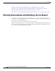
Preface Purpose This guide describes the hardware features of the Catalyst 3750-X and 3560-X switches. It describes the physical and performance characteristics of each switch, explains how to install a switch, and provides troubleshooting information. This guide does not describe system messages that you might receive or how to configure your switch. See the switch software configuration guide, the switch command reference, and the switch system message guide on http://www.cisco.
Preface Information about Cisco SFP and SFP+ modules is available from this Cisco.com site: http://www.cisco.com/en/US/products/hw/modules/ps5455/prod_installation_guides_list.html SFP compatibility matrix documents are available from this Cisco.com site: http://www.cisco.com/en/US/products/hw/modules/ps5455/products_device_support_tables_list.
C H A P T E R 1 Product Overview The Catalyst 3750-X and 3560-X series switches are Ethernet switches to which you can connect devices such as Cisco IP Phones, Cisco Wireless Access Points, workstations, and other network devices such as servers, routers, and other switches. The Catalyst 3750-X switches support stacking through Cisco StackWise technology and power management through StackPower. The Catalyst 3560-X switches do not support switch stacking or StackPower.
Chapter 1 Product Overview Switch Models Table 1-1 Catalyst 3750-X Switch Models (continued) Switch Model Cisco IOS Image 3 Description Catalyst 3750-X-48T-S IP Base image 48 10/100/1000 Ethernet ports, StackWise Plus, StackPower, 1 network module1 slot, 350-W power supply Catalyst 3750-X-24P-S IP Base image3 24 10/100/1000 PoE+2 ports, StackWise Plus, StackPower, 1 network module1 slot, 715-W power supply Catalyst 3750-X-48P-S IP Base image3 48 10/100/1000 PoE+2 ports, StackWise Plus, Stack
Chapter 1 Product Overview Front Panel Description 3. You can upgrade to the IP Services feature set when you order the switch. Front Panel Description The switch front panel includes a USB Type B console port, the 10/100/1000 Ethernet ports or the 10/100/1000 PoE+ ports, the network module, and the switch LEDs. Figure 1-1 shows the Catalyst 3750-X-48 PoE+ switch as an example. All the Catalyst 3750-X and 3560-X switches have similar components.
Chapter 1 Product Overview Front Panel Description • Configuration for StackPower PoE+.
Chapter 1 Product Overview Front Panel Description Table 1-3 Network Modules Network Module1 Description Blank This module has no uplink ports. 1-Gigabit Ethernet This module has four 1-Gigabit SFP module slots. Any combination of standard SFP modules are supported. SFP+ modules are not supported. If you insert an SFP+ module in the 1-Gigabit network module, the SFP+ module does not operate, and the switch logs an error message. 10-Gigabit Ethernet This module has four slots.
Chapter 1 Product Overview Front Panel Description Table 1-4 Cisco SFP Modules Supported for the 3750-X and 3560-X Switches Part Number Description GLC-GE-100FX= 100FX SFP on GE SFP ports for LAN switches1 GLC-LH-SM= GE SFP, LC connector LX/LH transceiver GLC-SX-MM= GE SFP, LC connector SX transceiver GLC-T= 1000BASE-T SFP transceiver module for copper connections GLC-ZX-SM= 1000BASE-ZX SFP module for SMF, 1550 nm GLC-BX-D= 1000BASE-BX10 SFP module for single-strand SMF, 1490-nm TX, 1310-n
Chapter 1 Product Overview Front Panel Description Table 1-4 Cisco SFP Modules Supported for the 3750-X and 3560-X Switches (continued) Part Number Description DWDM-SFP-4373= DWDM SFP 1543.73-nm SFP (100 GHz ITU grid) DWDM-SFP-4453= DWDM SFP 1544.53-nm SFP (100 GHz ITU grid) DWDM-SFP-4532= DWDM SFP 1545.32-nm SFP (100 GHz ITU grid) DWDM-SFP-4612= DWDM SFP 1546.12-nm SFP (100 GHz ITU grid) DWDM-SFP-4692= DWDM SFP 1546.92-nm SFP (100 GHz ITU grid) DWDM-SFP-4772= DWDM SFP 1547.
Chapter 1 Product Overview Front Panel Description Table 1-5 Cisco SFP+ Modules Supported for the 3750-X and 3560-X Switches Part Number Description SFP-H10GB-CU3M= 10 GBASE-CU Twinax SFP+ cable assembly, 3 meters SFP-H10GB-CU5M= 10 GBASE-CU Twinax SFP+ cable assembly, 5meters For information about SFP modules, see your SFP module documentation and the “Installing SFP and SFP+ Modules” section on page 2-25. For cable specifications, see Appendix B, “Connector and Cable Specifications.
Chapter 1 Product Overview Front Panel Description 2. Only Catalyst 3750-X switches. 3. Only switches with PoE+ ports. System LED Table 1-6 System LED Color System Status Off System is not powered on. Green System is operating normally. Blinking Green Switch is running power on self-test (POST). Blinking Amber There is a fault with one of the following: Amber • Network module (non-traffic-related) • Power supply • Fan module System is receiving power but is not functioning properly.
Chapter 1 Product Overview Front Panel Description When you press the Mode button on any switch in the Catalyst 3750-X switch stack, all the stack switches change to show the same selected mode. For example, if you press the Mode button on the stack master to show the SPEED LED, all the other switches in the stack also show the SPEED LED. Table 1-8 Port Mode LEDs Mode LED Port Mode Description STAT Port status The port status. This is the default mode.
Chapter 1 Product Overview Front Panel Description Table 1-9 Meaning of Switch LED Colors in Different Modes (continued) Port Mode Port LED Color Meaning DUPLX (duplex) Off Port is operating in half duplex. Green Port is operating in full duplex. MAST1 (data stack master) Off The switch is not the stack master. For a standalone switch, this LED is off. Note Green The switch is the stack master. Amber Error during stack master election.
Chapter 1 Product Overview Front Panel Description Table 1-10 USB Console Port LED Color Description Off USB console is disabled. Green USB console is enabled. S-PWR LED (Catalyst 3750-X) Table 1-11 S-PWR LED Color Description Off StackPower cable is not connected, or the switch is in standalone mode. Green An XPS cable is connected to the XPS-2200. Each StackPower port is connected to another switch or to an XPS-2200 (Catalyst 3750-X switches).
Chapter 1 Product Overview Front Panel Description Figure 1-3 Stack LED MODE CONSO LE SYST XPS EN SYST XPS STAT EN S-PWR SPEED 2 MODE 3 4 5 6 7 8 CONSO LE SYST XPS STAT EN S-PWR 9 10 11 MODE 4 5 6 7 8 CONSO LE SYST 3 4 5 6 7 PoE 8 9 10 11 C3KX-N 12 2 3 4 5 6 1 7 8 9 10 2 11 3 STAT S-PWR 9 10 SPEED MAST STACK 11 12 2 3 4 DUPLX 5 6 7 8 PoE 9 10 11 4 12 1 2 3 4 2 3 4 5 6 7 8 9 10 11 2 5 6 7 8 5 3 4 5 5 6 6
Chapter 1 Product Overview Front Panel Description Network Module LEDs Figure 1-4 Network Module LEDs (10-Gigabit Network Module Shown) C3KX-N NETWOR MODULEK 37 38 39 40 41 42 43 44 253212 M-10G 45 Catalys 46 t 3750-X 47 48 PoE+48 G1 G2/TE1 G3 G4/TE2 1 2 3 4 1 G1 LED 3 G3 LED 2 G2/TE1 LED 4 G4/TE2 LED Table 1-14 Network Module LEDs Color Network Module Link Status Off Link is off. Green Link is on, no activity. Blinking green Activity on a link, no faults.
Chapter 1 Product Overview Rear Panel Description Rear Panel Description The switch rear panel has a ground connector, an RJ-45 console port, an RJ-45 10/100 management port, a USB Type A connector, two StackWise connectors (only Catalyst 3750-X switches), two fan modules, an XPS-2200 connector, a StackPower connector (only Catalyst 3750-X switches), and two power supply module slots. See Figure 1-6, and the descriptions on the following pages.
Chapter 1 Product Overview Rear Panel Description 1 Ground connector 7 Fan modules 2 RJ-45 console port LED 8 XPS-2200 connector 3 RJ-45 console port 9 Power supply module slot (blank module shown) 4 RJ-45 10/100 management port 10 Power supply module (AC power supply module shown) 5 USB Type A connector 11 AC power (input) status LED 6 Reset button 12 Power supply (output) status LED RJ-45 Console Port LED Table 1-15 RJ-45 Console Port LED Color RJ-45 Console Port Status Off RS
Chapter 1 Product Overview Rear Panel Description • CAB-STACK-50CM-NH= (0.5-meter cable, nonhalogen) • CAB-STACK-1M-NH= (1-meter cable, nonhalogen) • CAB-STACK-3M-NH= (3-meter cable, nonhalogen) Power Supply Modules The 24- and 48-port switches are powered through one or two internal power supply modules. The “Switch Power Supply Modules” section on page 1-17 and Table 1-16 describe the supported power supply modules.
Chapter 1 Product Overview Rear Panel Description Table 1-16 Switch Power Supply Modules (continued) Power Supply Module 48-Port PoE+ Switch1 24-Port PoE+ Switch 48-Port Non-PoE+ Switch C3KX-PWR-350WAC= Spare Spare Primary or spare Primary or spare C3KX-PWR-440WDC= Primary or spare Primary or spare Primary or spare Primary or spare C3KX-PSBAY-BLNK Blank module Blank module Blank module 24-Port Non-PoE+ Switch Blank module 1. For full 15.
Chapter 1 Product Overview Rear Panel Description For information about replacing a power supply module, wiring a DC power supply module, and module specifications, see Chapter 3, “Power Supply and Fan Module Installation,” and Appendix A, “Technical Specifications.” Fan Modules The switch has two internal hot-swappable 12-V fan modules, each with two fans. The air circulation system consists of the fan modules and the power supply modules.
Chapter 1 Product Overview Rear Panel Description The nine ports on the XPS-2200 provide the power and management signals to the Catalyst 3750-X and 3560-X switches. Other switch models do not support this management communication. The XPS-2200 communicates with each switch through the 12-pin cable. All connected switches can simultaneously communicate with the XPS-2200.
Chapter 1 Product Overview Management Options Table 1-19 RJ-45 Console Port LED Color Description Off Inactive link Amber POST failure USB Mini-Type B Port The switch provides a USB mini-Type B console connection on the front panel, and the RJ-45 console port on the switch rear panel. Console output is always active on both connectors, but console input is active on only one connector at a time, with the USB connector taking precedence over the RJ-45 connector.
Chapter 1 Product Overview Management Options • Cisco IOS CLI You can configure and monitor the switch and switch cluster members from the CLI. You can access the CLI by connecting your management station directly to the switch console port or by using Telnet from a remote management station. See the switch command reference on Cisco.com for more information.
C H A P T E R 2 Switch Installation This chapter describes how to install and connect a Catalyst 3750-X or a 3560-X switch. It also includes planning and cabling considerations for stacking switches (only Catalyst 3750-X switches).
Chapter 2 Switch Installation Preparing for Installation Warning To prevent the switch from overheating, do not operate it in an area that exceeds the maximum recommended ambient temperature of 113•F (45•C). To prevent airflow restriction, allow at least 3 inches (7.6 cm) of clearance around the ventilation openings. Statement 17B Warning Before working on equipment that is connected to power lines, remove jewelry (including rings, necklaces, and watches).
Chapter 2 Switch Installation Preparing for Installation Warning Ultimate disposal of this product should be handled according to all national laws and regulations. Statement 1040 Warning For connections outside the building where the equipment is installed, the following ports must be connected through an approved network termination unit with integral circuit protection: 10/100/1000 Ethernet. Statement 1044 Warning Installation of the equipment must comply with local and national electrical codes.
Chapter 2 Switch Installation Planning a Switch Data Stack (Catalyst 3750-X Switches) • When connecting or disconnecting the power cord on a switch that is installed above or below a 1100-W power supply-equipped switch, you might need to remove the module from the switch to access the power cord. • Cabling is away from sources of electrical noise, such as radios, power lines, and fluorescent lighting fixtures. Make sure that the cabling is safely away from other devices that might damage the cables.
Chapter 2 Switch Installation Data Stack Cabling Configurations Switch Data Stacking Guidelines For general concepts and management procedures for switch stacks, see the switch software configuration guide on Cisco.com. When adding a Catalyst 3750-X switch to a Catalyst 3750 switch stack, review the Catalyst 3750-X Switch Stack Compatibility Guide on Cisco.com for information about mixed stack configurations.
Chapter 2 Switch Installation Data Stack Cabling Configurations STACK 1 STACK 2 STACK 1 STACK 2 STACK 1 STACK 2 STACK 1 STACK 2 STACK 1 STACK 2 STACK 1 STACK 2 STACK 1 STACK 2 STACK 1 STACK 2 STACK 1 STACK 2 Data Stacking the Switches in a Rack or on a Table Using the 0.5-meter StackWise Cable STACK 1 STACK 2 STACK 1 STACK 2 STACK 1 STACK 2 253200 Figure 2-1 The configuration examples in Figure 2-2 use a 3-meter StackWise cable and the supplied 0.5-meter StackWise cable.
Chapter 2 Switch Installation Data Stack Cabling Configurations Figure 2-3 shows a recommended configuration when the switches are mounted side-by-side. Use the 1-meter and the 3-meter StackWise cables to connect the switches. This configuration provides redundant connections. Data Stacking up to Eight Switches in a Side-by-Side Mounting 86825 Figure 2-3 Data Stack Bandwidth and Partitioning Examples This section provides examples of data stack bandwidth and possible data stack partitioning.
Chapter 2 Switch Installation Planning a StackPower Stack (Catalyst 3750-X Switches) 1 2 STACK 1 STACK 2 STACK 1 STACK 2 STACK 1 STACK 2 Example of a Partitioned Data Stack with a Failover Condition 253205 Figure 2-7 Power On Sequence for Switch Data Stacks Consider these guidelines before you power on the switches in a stack: • The sequence in which the switches are first powered on might affect the switch that becomes the stack master.
Chapter 2 Switch Installation StackPower Cabling Configurations For general concepts and management procedures for switch power stacks, see the switch software configuration guide on Cisco.com. Before connecting the switches in a power stack, keep in mind these guidelines: • A switch power stack can include a maximum of four switches in a ring topology and nine switches in a star topology with the XPS-2200. • Size of the switch and any optional power supply module. The 1100-W power-supply module is 1.
Chapter 2 Switch Installation StackPower Cabling Configurations Table 2-1 StackPower Cables Part Number Cable Type Length CAB-SPWR-30CM Catalyst 3750-X StackPower cable 0.3 meter CAB-SPWR-150CM Catalyst 3750-X StackPower cable 1.5 meter Figure 2-8 Table 2-2 StackPower Cable for Use Only with Catalyst 3750-X Switches XPS-2200 Cables Part Number Cable Type Length CAB-XPS-58CM XPS-2200 connector cable 0.58 meter CAB-XPS-150CM XPS-2200 connector cable 1.
Chapter 2 Switch Installation StackPower Cabling Configurations You can configure a ring power stack or use the XPS-2200 to configure a star topology. Figure 2-10 shows a ring configuration using both of the supplied 0.3-meter StackPower cables and one 1.5-meter cable. In these examples, the switches are stacked in a vertical rack or on a table.
Chapter 2 Switch Installation StackPower Cabling Configurations Figure 2-11 StackPower Star Topology Using the XPS-2200 PS OK WAC WR-715 C3KX-P AC OK PS OK WAC WR-715 C3KX-P AC OK S-PWR XPS PS OK C R-715WA C3K-PW AC OK AUX E CONSOL RESET S-PWR PS OK C R-715WA C3K-PW AC OK 1 STACK 2 STACK S-PWR XPS PS OK C R-715WA C3K-PW AC OK AUX E CONSOL RESET S-PWR PS OK C R-715WA C3K-PW AC OK 1 STACK 2 STACK S-PWR XPS PS OK C R-715WA C3K-PW AC OK AUX E CONSOL RESET S-PWR PS OK C R-7
Chapter 2 Switch Installation StackPower Cabling Configurations Figure 2-12 Power Stacking Catalyst 3750-X Switches within a Switch Data Stack PS OK WAC WR-715 C3KX-P AC OK PS OK WAC WR-715 C3KX-P AC OK S-PWR XPS PS OK AC OK AUX E CONSOL RESET S-PWR PS OK AC OK 1 STACK 2 STACK S-PWR XPS PS OK AC OK AUX E CONSOL RESET S-PWR PS OK AC OK 1 STACK 2 STACK S-PWR XPS PS OK AC OK AUX E CONSOL RESET S-PWR PS OK AC OK 1 STACK 2 STACK S-PWR XPS PS OK AC OK AUX E CONSOL RESET S-PWR PS
Chapter 2 Switch Installation Installing the Switch StackPower Partitioning Examples Figure 2-15 and Figure 2-16 show StackPower stacks of Catalyst 3750-X switches with failover conditions. In Figure 2-15, the StackPower cable 2 is faulty. Therefore, this stack does not provide redundancy.
Chapter 2 Switch Installation Installing the Switch Warning To prevent bodily injury when mounting or servicing this unit in a rack, you must take special precautions to ensure that the system remains stable. The following guidelines are provided to ensure your safety: • This unit should be mounted at the bottom of the rack if it is the only unit in the rack.
Chapter 2 Switch Installation Installing the Switch Figure 2-17 Rack-Mounting Brackets 1 2 3 4 253206 5 1 19-inch brackets, part number 700-29656-01 2 23-inch brackets, part number 700-31900-01 3 23/24-inch brackets, part number 700-31901-01 4 ETSI brackets, part number 700-31899-01 5 Extension rails and brackets for four-point mounting, kit part number 53-3408-01 Catalyst 3750-X and 3560-X Switch Hardware Installation Guide 2-16 OL-19593-01
Chapter 2 Switch Installation Installing the Switch Attaching the Rack-Mount Brackets To install the switch in a rack, use four Phillips flat-head screws to attach the long side of the brackets to the switch for the front- or rear-mounting positions (Figure 2-18). Use three screws to attach the brackets for the mid-mounting position.
Chapter 2 Switch Installation Installing the Switch 1 Front-mounting position 4 Rear-mounting position 2 Number-8 Phillips flat-head screws 5 Four-point mounting positions 3 Mid-mounting position Mounting the Switch in a Rack After the brackets are attached to the switch, use the supplied Phillips machine screws to attach the brackets to the rack (Figure 2-19). Use the black Phillips machine screw to attach the cable guide to the left or right bracket.
Chapter 2 Switch Installation Installing the Switch Figure 2-19 Mounting the Switch in a Rack 3 MODE CONSOL E SYST XPS STAT EN S-PWR SPEED MAST STACK 1 2 3 4 5 6 7 8 9 10 DUPLX PoE 11 12 13 14 15 16 17 18 19 20 21 22 23 C3KX-NM -10G 24 25 26 27 28 29 30 31 32 33 34 35 37 1 NETWOR MODULEK 36 38 39 40 41 42 43 2 44 45 46 Catalyst 47 48 3750-X PoE+48 G1 G2/TE1 G3 G4/TE2 4 5 MODE CONSOL E SYST XPS STAT EN S-PWR SPEED MAST STACK 1 2 3 4
Chapter 2 Switch Installation Installing the Switch When you complete the switch installation, see the “After Installing the Switch” section on page 2-21 for more information about switch configuration. Table- or Shelf-Mounting To install the switch on a table or shelf, locate the adhesive strip with the rubber feet in the mounting-kit envelope. Attach the four rubber feet to the recessed areas on the bottom of the chassis (See Figure 2-20).
Chapter 2 Switch Installation Connecting to the StackWise Ports (Catalyst 3750-X Switches) After Installing the Switch After the switch is installed, you might need to: • Configure the switch by running Express Setup to enter the initial switch configuration. For instructions, see the switch getting started guide that shipped with the switch and also on Cisco.com. • Use the CLI setup program to enter the initial switch configuration.
Chapter 2 Switch Installation Connecting to the StackPower Ports (Catalyst 3750-X Switches) Caution Removing and installing the StackWise cable can shorten its useful life. Do not remove and insert the cable more often than is absolutely necessary. When you need to remove the StackWise cable from the connector, make sure to fully unscrew the correct screws. When the connectors are not being used, replace the dust covers.
Chapter 2 Switch Installation Connecting the StackPower Ports to the XPS-2200 Connecting the StackPower Ports to the XPS-2200 Before connecting the StackPower cables, review the “Planning a StackPower Stack (Catalyst 3750-X Switches)” section on page 2-8. Always use a Cisco-approved StackPower cable to connect the switches. To prevent misconfiguration, the StackPower ports on the switch and the XPS-2200 are keyed and have colored stripes that match the keying and stripes on the StackPower cable ends.
Chapter 2 Switch Installation Installing a Network Module in the Switch Use only Cisco network modules and SFP or SFP+ modules with the switch. For information about supported SFP modules, see the “SFP and SFP+ Modules” section on page 1-5. For more information about installing, removing, cabling, and troubleshooting network modules, see the module documentation on Cisco.com. For module cable specifications, see Appendix B, “Connector and Cable Specifications.
Chapter 2 Switch Installation Installing SFP and SFP+ Modules Installing the Network Module in the Switch 37 C3KX-N M-10G G1 Caution G2/TE1 G3 38 39 4 5 6 7 8 9 10 11 12 253156 Figure 2-25 NETWOR MODULEK G4/TE2 Do not install the converter module with connected SFP modules or cables. Always remove any cables and modules before installing the converter module in the slot.
Chapter 2 Switch Installation Installing SFP and SFP+ Modules Installing an SFP Module Observe these general precautions: Warning Caution Class 1 laser product. Statement 1008 • Do not remove the dust plugs from the SFP modules or the rubber caps from the fiber-optic cable until you are ready to connect the cable. The plugs and caps protect the module ports and cables from contamination and ambient light. • Removing and installing an SFP module can shorten its useful life.
Chapter 2 Switch Installation Connecting Devices to the Ethernet Ports Figure 2-27 Network Module with SFP Modules Installed 1 2 C3KX-N 37 38 39 40 41 42 43 44 NETWOR MODULEK 253157 M-10G 45 Catalys 46 t 3750-X 47 48 PoE+48 G1 3 G2/TE1 G3 G4/TE2 4 1 Network module 3 Send (TX) optical bore 2 SFP modules 4 Receive (RX) optical bore Removing an SFP Module Step 1 Attach an ESD-preventive wrist strap to your wrist and to a bare metal surface.
Chapter 2 Switch Installation Connecting Devices to the Ethernet Ports 10/100/1000 Ethernet Port Connections The 10/100/1000 Ethernet ports use RJ-45 connectors with Ethernet pinouts. The maximum cable length is 328 feet (100 meters). The 100BASE-TX and 1000BASE-T traffic requires Category 5, Category 5e, or Category 6 UTP cable. The 10BASE-T traffic can use Category 3 or Category 4 cable. The autonegotiation feature is enabled by default on the switch.
Chapter 2 Switch Installation Where to Go Next You can use this application to calculate the power supply requirements for a specific PoE configuration. Enter the number and types of powered devices that you plan to attach to the switch, and the calculator shows the PoE or PoE+ power required and the system power consumption. You must be a registered Cisco.com user to access the Cisco Power Calculator. If you do not have a user ID or password, you can register: http://tools.cisco.
Chapter 2 Switch Installation Where to Go Next • Use the CLI to configure the switch as a member of a cluster or as an individual switch from the console. See the switch command reference on Cisco.com for information on using the CLI with the switch. • Start an SNMP application such as the CiscoView application.
C H A P T E R 3 Power Supply and Fan Module Installation • Power Supply Module Overview, page 3-1 • Installation Guidelines, page 3-5 • Installing an AC Power Supply, page 3-6 • Installing a DC Power Supply, page 3-7 • Finding the Power Supply Module Serial Number, page 3-12 • Fan Module Overview, page 3-14 • Installing a Fan Module, page 3-15 • Finding the Fan Module Serial Number, page 3-15 Power Supply Module Overview The switch operates with either one or two active power supply module
Chapter 3 Power Supply and Fan Module Installation Power Supply Module Overview Table 3-1 Power Supply Module Part Numbers and Descriptions Part Number Description C3KX-PWR-1100WAC= C3KX-PWR-1100WAC-JP=1 1100-W AC power supply module C3KX-PWR-715WAC= 715-W AC power supply module C3KX-PWR-350WAC= 350-W AC power supply module C3KX-PWR-440WDC= 440-W DC power supply module C3KX-PSBAY-BLNK Blank cover 1. This module is used only in Japan.
Chapter 3 Power Supply and Fan Module Installation Power Supply Module Overview Each AC power supply module has a power cord for connection to an AC power outlet. The 1100-W and 715-W modules use a 16-AWG cord (only North America). All other modules use an 18-AWG cord. The DC power supply module must be wired to a DC power source. Note Only the DC power module is NEBS-compliant. Figure 3-1 to Figure 3-4 show the power supply modules.
Chapter 3 Power Supply and Fan Module Installation Power Supply Module Overview Figure 3-3 350-W AC Power Supply Module 1 2 3 4 AC OK C3KX-PW R-350W AC 207488 PS OK 5 6 1 350-W AC power supply module 4 AC power cord connector 2 AC OK LED 5 Release latch 3 PS OK LED 6 Power cord retainer Figure 3-4 440-W DC Power Supply Module 1 2 3 DC OK 4 5 6 5 C3KX-PW R-440W DC 253562 PS OK 4 UT TP X OU MA W 44 /22A UT V 2 INP O-7 TA -36 /12 9 7 8 1 440-W DC power supply module 6
Chapter 3 Power Supply and Fan Module Installation Installation Guidelines Figure 3-5 Power Supply Slot Cover 253564 2 1 1 Release handles 2 Retainer clips The power supply modules have two status LEDs. Table 3-4 Switch Power Supply Module LEDs AC Power Supply Module LEDs AC OK Description PS OK Description Off (AC LED is off) No AC input power. Off Output is disabled, or input is outside operating range. Green AC input power present. Green Power output to switch.
Chapter 3 Power Supply and Fan Module Installation Installing an AC Power Supply • You can remove and replace the power supply when the switch is connected to an XPS-2200 without interrupting normal switch operation. After a delay of about 3 seconds, the switch power supply automatically provides power, and the XPS-2200 is available to power other devices. Caution Do not operate the switch with one power-supply module slot empty.
Chapter 3 Power Supply and Fan Module Installation Installing a DC Power Supply Caution Step 5 Do not leave the power-supply slot open for more than 90 seconds while the switch is operating. Insert the new power supply into the power-supply slot, and gently push it into the slot (Figure 3-6). When correctly inserted, the 350-W and 715-W power supplies (excluding the power cord retainer) are flush with the switch rear panel. The 1100-W power-supply module extends 1.5 inches from the switch rear panel.
Chapter 3 Power Supply and Fan Module Installation Installing a DC Power Supply Warning An exposed wire lead from a DC-input power source can conduct harmful levels of electricity. Be sure that no exposed portion of the DC-input power source wire extends from the terminal block plug. Statement 122 Warning Before connecting or disconnecting ground or power wires to the chassis, ensure that power is removed from the DC circuit.
Chapter 3 Power Supply and Fan Module Installation Installing a DC Power Supply Grounding the Switch Follow the grounding procedures at your site and observe these warnings: Warning This equipment must be grounded. Never defeat the ground conductor or operate the equipment in the absence of a suitably installed ground conductor. Contact the appropriate electrical inspection authority or an electrician if you are uncertain that suitable grounding is available.
Chapter 3 Power Supply and Fan Module Installation Installing a DC Power Supply Step 5 Use the ground screw to attach the single-ground lug to the switch rear panel. Use two ground screws to attach the dual-hole lug to the switch rear panel (Figure 3-10). Step 6 Using a ratcheting torque screwdriver, torque the ground-lug screws to 60 lbf-in. (960 ozf-in.). Step 7 Connect the other end of the grounding wire to an appropriate grounding point at your site or to the rack.
Chapter 3 Power Supply and Fan Module Installation Installing a DC Power Supply Figure 3-11 Inserting the DC Power Supply in the Switch CONSOL E AUX STACK 1 RESET STACK 2 S-PWR XPS AC OK PS OK C3KX-P WR-440 WDC S-PWR PS OK Step 6 253211 AC OK C3KX-P WR-440 WDC Connect the input power as described in the “Wiring the DC Input Power Source” section.
Chapter 3 Power Supply and Fan Module Installation Finding the Power Supply Module Serial Number Figure 3-13 DC Source A and Source B Connections with Common Ground A+ B- B+ + - - + 253446 A- Step 4 Torque all terminal block screws to 11 lbf-in. Step 5 Replace the terminal block safety cover. Step 6 Move the DC power source circuit-breakers to the ON position. Step 7 Confirm that the power-supply DC OK and PS OK LEDs are green. See Table 3-4 for a description of the module LEDs.
Chapter 3 Power Supply and Fan Module Installation Finding the Power Supply Module Serial Number Figure 3-15 715-W and 350-W AC Power Supply Module Serial Number 277561, 781-00668-01 SN: XXXNNNNXXXX C3K X-P WR -715 WA C Catalyst 3750-X and 3560-X Switch Hardware Installation Guide OL-19593-01 3-13
Chapter 3 Power Supply and Fan Module Installation Fan Module Overview Figure 3-16 440-W DC Power Supply Module Serial Number 277562, 781-00667-01 SN: XXXNNNNXXXX C3K X-P WR -4 40W DC Fan Module Overview The switch has two fan modules. Each fan module contains two fans. Fan modules are hot-swappable.
Chapter 3 Power Supply and Fan Module Installation Installing a Fan Module 1 Fan LED 3 Retainer clip 2 Exhaust vent 4 Extraction handles Installing a Fan Module Note Step 1 Caution Step 2 Warning There must be a fan module in both fan module slots. Pinch the fan release handle, and slide the fan out. You should replace a failed fan module within 5 minutes to avoid overheating the switch.
Chapter 3 Power Supply and Fan Module Installation Finding the Fan Module Serial Number Figure 3-19 Fan Module Serial Number 277564, 781-00666-01 SN: XXXNNNNXXXX Catalyst 3750-X and 3560-X Switch Hardware Installation Guide 3-16 OL-19593-01
C H A P T E R 4 Troubleshooting • Diagnosing Problems, page 4-1 • Resetting the Switch to the Factory Default Settings, page 4-5 • Finding the Switch Serial Number, page 4-6 • Replacing a Failed Data Stack Member (Catalyst 3750-X Switches), page 4-6 Diagnosing Problems The switch LEDs provide troubleshooting information about the switch. They show POST failures, port-connectivity problems, and overall switch performance.
Chapter 4 Troubleshooting Diagnosing Problems Switch Connections Bad or Damaged Cable Always examine the cable for marginal damage or failure. A cable might be just good enough to connect at the physical layer, but it could corrupt packets as a result of subtle damage to the wiring or connectors. You can identify this situation because the port has many packet errors or the port constantly flaps (loses and regains link). • Exchange the copper or fiber-optic cable with a known good cable.
Chapter 4 Troubleshooting Diagnosing Problems 10/100/1000 Port Connections A port appears to malfunction: • Verify the status of all ports. See Table 1-8 on page 1-10 for descriptions of the LEDs and their meanings. • Use the show interfaces privileged EXEC command to see if the port is error-disabled, disabled, or shut down. Re-enable the port if necessary. • Verify the cable type. See Appendix B, “Connector and Cable Specifications.
Chapter 4 Troubleshooting Diagnosing Problems Note When ordering or using CX1 cables, ensure that the version identifier is 2 or higher. • For long wave SFP+ modules, a mode conditioning patch might improve performance over maximum link distances with MMF connections. Interface Settings Verify that the port or interface is not disabled or powered off. If a port or interface is manually shut down on either side of the link, it does not come up until you re-enable the interface.
Chapter 4 Troubleshooting Resetting the Switch to the Factory Default Settings Autonegotiation and Network Interface Cards Problems sometimes occur between the switch and third-party network interface cards (NICs). By default, the switch ports and interfaces autonegotiate.Laptops or other devices are commonly set to autonegotiate, yet sometimes issues occur. To troubleshoot autonegotiation problems, try manually setting both sides of the connection.
Chapter 4 Troubleshooting Finding the Switch Serial Number Finding the Switch Serial Number If you contact Cisco Technical Assistance, you need to know the switch serial number. Figure 4-1 shows the serial number location. You can also use the show version privileged EXEC command to see the switch serial number.
A P P E N D I X A Technical Specifications • Switch Specifications, page A-1 • Power Supply Module Specifications, page A-2 • Fan Module Specifications, page A-4 Switch Specifications Table A-1 Environmental and Physical Specifications Environmental Ranges Operating temperature 32 to 113° F (0 to 45° C) Storage temperature –13 to 158° F (–25 to 70° C) Relative humidity 10 to 85% (noncondensing) Operating altitude Up to 10,000 ft (3049 m) Storage altitude Up to 15,000 ft (4573 m), NEBS up
Appendix A Technical Specifications Power Supply Module Specifications Table A-1 Environmental and Physical Specifications (continued) Weight Catalyst 3750-X-24T Catalyst 3750-X-24P Catalyst 3750-X-48T Catalyst 3750-X-48P Catalyst 3750-X-48PF Catalyst 3560-X-24T Catalyst 3560-X-24P Catalyst 3560-X-48T Catalyst 3560-X-48P Catalyst 3560-X-48PF 15.6 lb (7.1 kg)1 15.8 lb (7.2 kg)2 16.3 lb (7.4 kg)1 16.5 lb (7.5 kg)2 16.7 lb (7.6 kg)3 15.4 lb (7.0 kg)1 15.7 lb (7.1 kg)2 16.1 lb (7.3 kg)1 16.4 lb (7.
Appendix A Technical Specifications Power Supply Module Specifications Table A-2 Environmental and Physical Specifications for the AC- and DC-Power Supply Modules (continued) Weight C3KX-PWR-1100WAC 3 lb (1.4 kg) C3KX-PWR-715WAC 2.8 lb (1.3 kg) C3KX-PWR-350WAC 2.7 lb (1.2 kg) C3KX-PWR-440WDC 3.5 lb (1.6 kg) Dimensions (H x D x W) C3KX-PWR-1100WAC 1.38 x 11.72 x 3.25 in. (3.5 x 29.8 x 8.3 cm) C3KX-PWR-715WAC 1.38 x 10.22 x 3.25 in. (3.5 x 26 x 8.3 cm) C3KX-PWR-350WAC 1.38 x 10.22 x 3.25 in.
Appendix A Technical Specifications Fan Module Specifications Table A-4 Power Specifications for DC-Power 24- and 48-Port Switches Power Specifications Maximum output power C3KX-PWR-440WDC: 440 W Input current C3KX-PWR-440WDC: 16 – 8 A DC input voltage C3KX-PWR-440WDC: –36 to –72 VDC Output ratings C3KX-PWR-440WDC: –56 V@7.
Appendix A Technical Specifications Fan Module Specifications Table A-6 Standards and Certifications Description Specification Electromagnetic compatibility certifications FCC Part 15 Class A EN55022 Class A (CISPR22) EN55024 (CISPR24) CE VCCI Class A AS/NZS CISPR22 Class A MIC China EMC certifications GOST Environmental Reduction of Hazardous Substances (ROHS) 5 Noise specifications Office product spec: 48 dBA at 86º F (30º C) Telco CLEI code Catalyst 3750-X and 3560-X Switch Hardware Install
Appendix A Technical Specifications Fan Module Specifications Catalyst 3750-X and 3560-X Switch Hardware Installation Guide A-6 OL-19593-01
A P P E N D I X B Connector and Cable Specifications • “Connector Specifications” section on page B-1l • “Cable and Adapter Specifications” section on page B-5 Connector Specifications • 10/100/1000 Ports, page B-1 • 10 Gigabit Ethernet CX1 (SFP+ Copper) Connectors, page B-2 • SFP and SFP+ Modules, page B-2 • 10/100 Ethernet Management Port, page B-3 • Console Port, page B-4 10/100/1000 Ports The 10/100/1000 Ethernet ports on switches use RJ-45 connectors and Ethernet pinouts.
Appendix B Connector and Cable Specifications Connector Specifications 10 Gigabit Ethernet CX1 (SFP+ Copper) Connectors The 10-Gigabit Ethernet electrical modules use CX1 copper connectors similar to the one shown in Figure B-2. Note When ordering or using CX1 cables, ensure that the version identifier is 2 or higher. The 10-Gigabit Ethernet optical modules use the connectors shown in Figure B-3 and Figure B-4.
Appendix B Connector and Cable Specifications Connector Specifications Simplex LC Cable Connector Figure B-5 Copper SFP Module RJ-45 Connector 57834 Figure B-4 Label 1 TP0+ 2 TP0- 3 TP1+ 4 TP2+ 5 TP2- 6 TP1- 7 TP3+ 8 TP3- SFP Module Patch Cable (Catalyst 3560-X Switches) 126809 Figure B-6 1 2 3 4 5 6 7 8 60915 Pin 10/100 Ethernet Management Port The 10/100 Ethernet management port uses RJ-45 connectors with Ethernet pinouts. Figure B-7 shows the pinouts.
Appendix B Connector and Cable Specifications Connector Specifications 10/100 Port Pinouts Pin Label 1 RD+ 2 RD- 3 TD+ 4 NC 5 NC 6 TD- 7 NC 8 NC 1 2 3 4 5 6 7 8 H5318 Figure B-7 Console Port The switch has two console ports: a USB 5-pin mini-Type B port on the front panel (see Figure B-8) and an RJ-45 console port on the rear panel. USB Mini-Type B Port 253163 Figure B-8 The USB console port uses a USB Type A to 5-pin mini-Type B cable, shown in Figure B-9.
Appendix B Connector and Cable Specifications Cable and Adapter Specifications The RJ-45 console port uses an 8-pin RJ-45 connector (See Table B-2 and Table B-3.) The supplied RJ-45-to-DB-9 adapter cable is used to connect the console port of the switch to a console PC. You need to provide a RJ-45-to-DB-25 female DTE adapter if you want to connect the switch console port to a terminal. You can order a kit (part number ACS-DSBUASYN=) containing that adapter.
Appendix B Connector and Cable Specifications Cable and Adapter Specifications Table B-1 Fiber-Optic SFP and SFP+ Module Port Cabling Specifications (continued) Wavelength (nanometers) SFP Module Cable Type Core Size/Cladding Size (micron) Modal Bandwidth (MHz/km)1 Cable Distance 1000BASE-T (GLC-T) Standard 4 twisted-pair Category 5 cable — — — 328 feet (100 m) 1000BASE-LX/LH (GLC-LH-SM) 1310 MMF3 SMF 62.5/125 50/125 50/125 G.
Appendix B Connector and Cable Specifications Cable and Adapter Specifications Four Twisted-Pair Cable Pinouts Router or PC 1 TPO+ 1 TP1+ 2 TPO- 2 TP1- 3 TP1+ 3 TPO+ 6 TP1- 6 TPO- 4 TP2+ 4 TP3+ 5 TP2- 5 TP3- 7 TP3+ 7 TP2+ 8 TP3- 8 TP2- Figure B-11 65272 Switch Four Twisted-Pair Straight-Through Cable Schematic Four Twisted-Pair Crossover Cable Schematic Switch Switch 1 TP0+ 1 TP0+ 2 TP0- 2 TP0- 3 TP1+ 3 TP1+ 6 TP1- 6 TP1- 4 TP2+ 4 TP2+ 5 TP2- 5 TP2- 7 TP3+ 7 TP3+ 8 TP
Appendix B Connector and Cable Specifications Cable and Adapter Specifications Two Twisted-Pair Crossover Cable Schematic Switch Switch 3 TD+ 6 TD– 3 TD+ 6 TD– 1 RD+ 2 RD– 1 RD+ 2 RD– H5579 Figure B-13 Identifying a Crossover Cable To identify a crossover cable, hold the cable ends side-by-side, with the tab at the back. The wire connected to the pin on the outside of the left plug should be the same color as the wire connected to the pin on the outside of the right plug. (See Figure B-14.
Appendix B Connector and Cable Specifications Cable and Adapter Specifications Table B-2 Console Port Signaling Using a DB-9 Adapter (continued) Switch Console Port (DTE) RJ-45-to-DB-9 Terminal Adapter Console Device Signal DB-9 Pin Signal GND 5 GND GND 5 GND RxD 3 TxD DSR 4 DTR CTS 7 RTS Table B-3 lists the pinouts for the console port, RJ-45-to-DB-25 female DTE adapter, and the console device. Note The RJ-45-to-DB-25 female DTE adapter is not supplied with the switch.
Appendix B Connector and Cable Specifications Cable and Adapter Specifications Catalyst 3750-X and 3560-X Switch Hardware Installation Guide B-10 OL-19593-01
A P P E N D I X C Configuring the Switch with the CLI-Based Setup Program This appendix provides a CLI-based setup procedure for a Catalyst 3750-X and 3560-X standalone switch or a switch stack. To set up the switch by using Express Setup, see the Cisco 3750-X and 3560-X Switch Getting Started Guide. Before connecting the switch to a power source, review the safety warnings in Chapter 2, “Switch Installation.
Appendix C Configuring the Switch with the CLI-Based Setup Program Accessing the CLI Note If you have stacked Catalyst 3750-X switches, connect to the 10/100 Ethernet management port or console port of one of the stack switches. You can perform the initial configuration for the entire stack on any switch in the stack. Use one of these options to access the CLI: • RJ-45 Console Port • USB Console Port RJ-45 Console Port The RJ-45 console port is on the rear panel of the switch.
Appendix C Configuring the Switch with the CLI-Based Setup Program Accessing the CLI Connecting the USB Console Cable to the Catalyst 3750-X or 3560-X Switch CONSOL E MODE SYST XPS EN STAT S-PWR 1 2 3 4 5 6 MAST 7 8 SPEED STACK 9 10 DUPLX PoE 11 12 253406 Figure C-1 Step 2 Connect a USB cable to the PC USB port. Connect the other end of the cable to the switch mini-B (5-pin-connector) USB console port. See Figure C-1.
Appendix C Configuring the Switch with the CLI-Based Setup Program Accessing the CLI Installing the Cisco Microsoft Windows XP USB Driver Step 1 Obtain the file Cisco_usbconsole_driver.zip from the Cisco.com web site and unzip it. Note You can download the driver file from the Cisco.com site for downloading the switch software. Step 2 If using 32-bit Windows XP, double-click the setup.exe file in the Windows_32 folder. If using 64-bit Windows XP, double-click the setup(x64).
Appendix C Configuring the Switch with the CLI-Based Setup Program Accessing the CLI Note If a User Account Control warning appears, click Allow - I trust this program to proceed. Step 5 The InstallShield Wizard Completed window appears. Click Finish. Step 6 Connect the USB cable to the PC and the switch console port. The USB console port LED turns green, and the Found New Hardware Wizard appears. Follow the instructions to complete the driver installation.
Appendix C Configuring the Switch with the CLI-Based Setup Program Entering the Initial Configuration Information Uninstalling the Cisco Microsoft Windows Vista and Windows 7 USB Driver Note Disconnect the switch console terminal before uninstalling the driver. Step 1 Run setup.exe for Windows 32-bit or setup(x64).exe for Windows-64bit. Click Next. Step 2 The InstallShield Wizard for Cisco Virtual Com appears. Click Next.
Appendix C Configuring the Switch with the CLI-Based Setup Program Entering the Initial Configuration Information Would you like to enter the initial configuration dialog? [yes/no]: yes At any point you may enter a question mark '?' for help. Use ctrl-c to abort configuration dialog at any prompt. Default settings are in square brackets '[]'. Basic management setup configures only enough connectivity for management of the system, extended setup will ask you to configure each interface on the system.
Appendix C Configuring the Switch with the CLI-Based Setup Program Entering the Initial Configuration Information If you enter N, the switch appears as a candidate switch in the Network Assistant GUI. You can configure the switch as a command switch later through the CLI, the device manager, or the Network Assistant application. To configure it later, enter no.
INDEX Numerics C 10/100/1000 ports cable guide, attaching cable lengths 1-3, 2-28 cable lengths connecting to 2-28 cables described pinouts 2-18 B-5 crossover 1-3 four twisted-pair pinout B-1 recommended cables identifying 2-28 10/100 Ethernet management port 10-Gigabit Ethernet module slots connecting devices 19- and 24-inch racks B-8 two twisted-pair pinout 1-20 patch cable B-7 B-2 recommended 2-24 B-7 2-28 StackWise 2-18 cable numbers connecting to A 1-16 2-21, 2-22, 2
Index crossover cable F See cables fan module airflow patterns D DC power power-supply module described specifications 3-8 diagnosing problems clearance 2-3 described 1-3 to 1-14 PoE+ ports 4-1 1-3 1-8 to 1-14 network modules 2-29 1-5 1-3 A-3 duplex G default setting LED 3-15 LEDs 1-21 to configure switch dimensions installing 10/100/1000 Ethernet ports device manager described 1-19 front panel 1-17 A-4 DC power warning described 1-19 2-28 ground connection 1-10 troub
Index J N jewelry removal warning NEBS standard for electromagnetic safety 2-2 Network Assistant 2-3 2-29 Network Equipment Building Systems L See NEBS network modules LEDs color meanings duplex port noise, electrical 1-8 to 1-14 interpreting master 2-4 O 1-10 outside connections warning 1-9 to 1-12 port mode overheating warning 1-9 to 1-11 POST results speed 1-10 stack 1-12 2-3 2-2 4-1 P StackPower system 2-24 1-9 1-12 STATUS 1-5 installation 1-10 front panel PoE+
Index PoE+ (continued) rear panel (continued) troubleshooting StackWise ports 4-3 port and interface troubleshooting port LEDs port modes changing LEDs XPS connector 4-4 1-9 to 1-12 1-16 1-19 restricted access area warning 2-2 RJ-45 connector, console port B-5 RJ-45 console port 1-8 LED 1-9 to 1-10 1-15, 1-16 1-20 See also mode button ports S 10/100/1000 connecting to described pinouts 2-28 safety 1-3 serial number location B-1 2-28 POST 4-1 2-2 SFP+ modules supported 1-7 SF
Index SunNet Manager switch models system LED 1-22 W 1-1 warnings 1-9 code compliance 2-3 connecting outside of building T connecting the power table-mounting DC power 2-20 technical specifications telco racks A-1 2-18 Telnet, and accessing the CLI temperature, operating 3-8 2-3 ground connection 3-9 2-1 lightning activity A-1 transceiver troubleshooting overheating 4-3 2-2 2-2 PoE+ shock hazard troubleshooting bad or damaged cable 2-29 preventing bodily injury 4-2 connect
Index Catalyst 3750-X and 3560-X Switch Hardware Installation Guide IN-6 OL-19593-01