Installation and Upgrade Guide for Cisco Unified Videoconferencing 3545 PRI Gateway and 3545 Serial Gateway Release 5.6 August 2008 Americas Headquarters Cisco Systems, Inc. 170 West Tasman Drive San Jose, CA 95134-1706 USA http://www.cisco.
THE SPECIFICATIONS AND INFORMATION REGARDING THE PRODUCTS IN THIS MANUAL ARE SUBJECT TO CHANGE WITHOUT NOTICE. ALL STATEMENTS, INFORMATION, AND RECOMMENDATIONS IN THIS MANUAL ARE BELIEVED TO BE ACCURATE BUT ARE PRESENTED WITHOUT WARRANTY OF ANY KIND, EXPRESS OR IMPLIED. USERS MUST TAKE FULL RESPONSIBILITY FOR THEIR APPLICATION OF ANY PRODUCTS.
CONTENTS CHAPTER 1 Functionality 1-1 About Cisco Unified Videoconferencing 3545 Gateway Products About Gateway Features 1-1 1-2 About Cisco Unified Videoconferencing 3545 Gateway Applications and Topologies About Multimedia Conferencing 1-7 About Point-to-Point Conferencing 1-8 About Multipoint Conferencing 1-8 About Gateway IP Network Connections 1-9 About Gateway ISDN Network Connections 1-9 About Gateway Encryption 1-11 About Conferencing via Leased Lines 1-12 About IP-to-Legacy MCU Conferencing 1
Contents Setting the IP Address 2-11 Setting Ethernet Speed and Duplex Parameters 2-13 Changing the Configuration Tool Login Password 2-14 Upgrading Gateway Software 2-14 Connecting the Gateway to the Network Connecting PRI Lines to the Gateway 2-15 2-15 Connecting Serial Lines to the Gateway 2-15 Serial Gateway Cable Connections and Pin-outs 2-16 Physical Description of DTE Cables 2-16 Physical Description of DCE Cables 2-20 Data Interface Cable Pin-out Configurations 2-22 Data Interface Pin Layouts
Contents High Voltage 6-2 Power Supply 6-2 ESD Procedures 6-2 Batteries 6-3 Sicherheit 6-4 Elektrische Sicherheit 6-4 Erdung 6-4 Hochspannung 6-4 Netzteil 6-4 ESD-Verfahren 6-5 Warnhinweise 6-5 Seguridad 6-6 Seguridad Electrica 6-6 Tierra 6-6 Alto Voltage 6-6 Abastecimiento de Electricidad Procedimientos ESD Securite 6-6 6-7 6-8 Securite Electrique 6-8 Mise a la Terre 6-8 Haute Tension 6-9 Alimentation Electrique 6-9 Prevention des Decharges Electrostatiques CHAPTER 7 Compliance and Certif
Contents Installation and Upgrade Guide for Cisco Unified Videoconferencing 3545 PRI Gateway and 3545 Serial Gateway Release 5.
CH A P T E R 1 Functionality • About Cisco Unified Videoconferencing 3545 Gateway Products, page 1-1 • About Gateway Features, page 1-2 • About Cisco Unified Videoconferencing 3545 Gateway Applications and Topologies, page 1-6 • About Cisco Unified Videoconferencing 3545 Gateway Functionality, page 1-13 About Cisco Unified Videoconferencing 3545 Gateway Products Cisco Unified Videoconferencing 3545 Gateway series consists of these products: • Cisco Unified Videoconferencing 3545 PRI Gateway The C
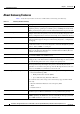
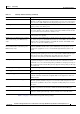
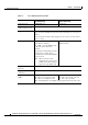
Chapter 1 Functionality About Gateway Features About Gateway Features Table 1-1 lists the major features of the Cisco Unified Videoconferencing 3545 Gateway. Table 1-1 Gateway Feature Summary Feature Description Interoperability The gateway provides a high degree of interoperability with other H.323 compliant gateways, gatekeepers, terminals, proxy, and Multipoint Control Unit (MCU) products by being based on the H.320 standard and H.323 protocol stack.
Chapter 1 Functionality About Gateway Features Table 1-1 Gateway Feature Summary (continued) Feature Description Dual video The gateway supports H.239 standards-based dual video and TANDBERG DuoVideo technology. Dual video streams enable a screen to carry video images from one source while simultaneously displaying images from a second source. Hot swap The gateway features hot swap functionality that you can use to remove and replace gateway cards under power.
Chapter 1 Functionality About Gateway Features Table 1-2 Cisco Gateway Feature Specifics Feature Cisco Unified Videoconferencing 3545 PRI Gateway Cisco Unified Videoconferencing 3545 Serial Gateway Supported ports 2 PRI ISDN ports 4 serial ports Supported video conferencing protocols H.320, H.323 (using Cisco Stack v4.
Chapter 1 Functionality About Gateway Features Table 1-2 Cisco Gateway Feature Specifics (continued) Feature Cisco Unified Videoconferencing 3545 PRI Gateway Cisco Unified Videoconferencing 3545 Serial Gateway Call handling capabilities For 1 x PRI T1 line: 1 call per serial connection, up to a maximum bandwidth of 1920 Kbps per port.
Chapter 1 Functionality About Cisco Unified Videoconferencing 3545 Gateway Applications and Topologies Table 1-2 Cisco Gateway Feature Specifics (continued) Feature Cisco Unified Videoconferencing 3545 PRI Gateway Cisco Unified Videoconferencing 3545 Serial Gateway Encryption interoperability N/A KIV-7, KG-194 PRI interface Configurable E1/T1 PRI network interface. N/A Support for fractional E1/T1 channel selection. Configurable as terminal side (TE) or network side (NT) device.
Chapter 1 Functionality About Cisco Unified Videoconferencing 3545 Gateway Applications and Topologies About Multimedia Conferencing The Cisco PRI gateway enables H.323 endpoints on the IP network to communicate with an H.320 terminal, an ISDN phone, or a regular phone on a circuit-switched public network without having to connect directly to these networks. The gateway allows all IP network terminals to support video conferences without connecting every desktop computer to an ISDN line (see Figure 1-1).
Chapter 1 Functionality About Cisco Unified Videoconferencing 3545 Gateway Applications and Topologies About Point-to-Point Conferencing The Cisco PRI gateway enables direct video, voice, and data communication between an H.320 (ISDN) terminal and H.323 (IP) terminals at bandwidths of up to 1472 Kbps (23B bonding for T1) and up to 1920 Kbps (30B bonding for E1). Figure 1-2 Point-to-Point Conferencing through the Gateway H.323 terminal IP network ISDN Cisco chassis/unit with serial gateway H.
Chapter 1 Functionality About Cisco Unified Videoconferencing 3545 Gateway Applications and Topologies Figure 1-3 Mixed ISDN-IP Multipoint Multimedia Conference IP network H.323 Terminal IP IP phone H.320 Terminal H.323 Terminal ISDN H.323 Terminal Cisco Unified Videoconferencing 3545 chassis with MCU and Gateway modules IP IP phone H.320 Terminal H.320 Terminal 281206 H.323 Terminal H.
Chapter 1 Functionality About Cisco Unified Videoconferencing 3545 Gateway Applications and Topologies PRI Gateways You can connect the PRI gateway directly to a PRI line provided by your local ISDN provider (as shown in Figure 1-4), or to a local private branch exchange (PBX) that provides the PRI connection (as shown in Figure 1-5). Figure 1-4 Connecting the PRI Gateway Directly to a Central Office Switch Private Public IP network PRI T1/E1 H.
Chapter 1 Functionality About Cisco Unified Videoconferencing 3545 Gateway Applications and Topologies About Gateway Encryption The serial gateway enables encrypted videoconferencing between H.323 endpoints on the IP network and endpoints on remote sites by connecting to external encryption/decryption devices via serial interfaces (as shown in Figure 1-6). The serial gateway also enables encrypted videoconferencing via satellite with or without RS-366 signaling (as shown in Figure 1-7).
Chapter 1 Functionality About Cisco Unified Videoconferencing 3545 Gateway Applications and Topologies About Conferencing via Leased Lines The serial gateway enables conferencing between H.323 endpoints on IP networks connected via a leased line (as shown in Figure 1-8). Figure 1-8 Conferencing via Leased Lines H.323 endpoint IP network IP network Adaptor V35. DCE DTE Cisco chassis/unit with serial gateway Cisco chassis/unit with serial gateway 157170 H.323 endpoint Adaptor Leased line V35.
Chapter 1 Functionality About Cisco Unified Videoconferencing 3545 Gateway Functionality About Cisco Unified Videoconferencing 3545 Gateway Functionality • About PRI Gateway Call Handling Capacity, page 1-13 • About Gateway Call Bandwidth Overhead, page 1-13 • About Peer-to-Peer Connectivity, page 1-14 About PRI Gateway Call Handling Capacity Table 1-3 lists the maximum call handling capacity of the PRI gateway for different types of calls.
Chapter 1 Functionality About Cisco Unified Videoconferencing 3545 Gateway Functionality Resource Allocation across E1/T1 Lines The gateway can allocate bandwidth resources to calls across separate E1 or T1 connections to maximize bandwidth capacity in cases where there is not enough capacity for a call on a single E1 or T1 connection, but where sufficient capacity does exist when remaining capacity on both E1/T1 lines is combined.
CH A P T E R 2 Installing the Cisco Unified Videoconferencing 3545 Gateway • Physical Description, page 2-1 • Requirements for Installation, page 2-3 • Verifying the Package Contents, page 2-4 • Mounting the Cisco Unified Videoconferencing 3545 Chassis in a 19-inch Rack, page 2-5 • How to Install the Gateway, page 2-6 • How to Perform the Initial Gateway Configuration, page 2-10 • Connecting the Gateway to the Network, page 2-15 • Connecting PRI Lines to the Gateway, page 2-15 • Connectin
Chapter 2 Installing the Cisco Unified Videoconferencing 3545 Gateway Physical Description Gateway Front Panel GK Reg CD SERIAL RST 10/100Base T-1 Table 2-1 157269 Figure 2-1 SWAP RDY ALARM ACT Front Panel Components Component Description 10/100 Base T-1 connector An RJ-45 connector that provides the primary Ethernet connection for the IP network port. SERIAL connector A DB-9 connector that allows you to connect a PC terminal for local configuration.
Chapter 2 Installing the Cisco Unified Videoconferencing 3545 Gateway Requirements for Installation Table 2-2 PRI Gateway Rear Transition Module Components (continued) Component Description ALARM LEDs Displays alarm events for the PRI line. PRI LINE connectors • YELLOW —Lights yellow when there is a loss of frame alignment at the remote side. • ORANGE—Lights orange when there is a loss of frame alignment in the gateway.
Chapter 2 Installing the Cisco Unified Videoconferencing 3545 Gateway Verifying the Package Contents • A PC with a serial port and terminal emulation software to assign the gateway an IP address • Dedicated IP address for the gateway • The IP address of the router the gateway will use to communicate across the network • The IP address of the H.
Chapter 2 Installing the Cisco Unified Videoconferencing 3545 Gateway Mounting the Cisco Unified Videoconferencing 3545 Chassis in a 19-inch Rack • V.35/RS366-DCE cable • EIA449/RS366-DCE cable • EIA530/RS366-DCE cable Related Topics • Serial Gateway Cable Connections and Pin-outs, page 2-16 Mounting the Cisco Unified Videoconferencing 3545 Chassis in a 19-inch Rack You can optionally mount the Cisco Unified Videoconferencing 3545 chassis in a standard 19-inch rack.
Chapter 2 Installing the Cisco Unified Videoconferencing 3545 Gateway How to Install the Gateway Step 6 Fasten the brackets to the side rails of the rack. Step 7 Make sure that the air vents at the sides of the Cisco Unified Videoconferencing 3545 chassis are not blocked.
Chapter 2 Installing the Cisco Unified Videoconferencing 3545 Gateway How to Install the Gateway Before working on a system that has an on/off switch, turn OFF the power and unplug the power cord. Before opening the chassis, disconnect the telephone network cables to avoid contact with telephone network voltages. To avoid electric shock, do not connect safety extra-low voltage (SELV) circuits to telephone-network voltage (TNV) circuits. LAN ports contain SELV circuits, and WAN ports contain TNV circuits.
Chapter 2 Installing the Cisco Unified Videoconferencing 3545 Gateway How to Install the Gateway Caution Do not force the connection. Forcing the connection can bend or damage the pins in the connector inside the chassis. Step 8 Snap the handles forward to secure the RTM module in the slot. Step 9 Secure the RTM module screws.
Chapter 2 Installing the Cisco Unified Videoconferencing 3545 Gateway How to Install the Gateway Note If you are installing the gateway module and the power to the chassis is on, the SWAP RDY LED on the module front panel turns blue when you slide the module into the chassis as far as it will go. This means that you can secure the module safely. The LED turns off when the handles are closed. Step 8 Snap the handles forward to secure the gateway module in the slot.
Chapter 2 Installing the Cisco Unified Videoconferencing 3545 Gateway How to Perform the Initial Gateway Configuration Removing a Module from the Cisco Unified Videoconferencing 3545 Chassis 157279 Figure 2-6 Step 3 Wait for the blue SWAP RDY LED to light up. The SWAP RDY LED indicates that it is safe to remove the module. It may take up to one minute for the LED to light up while the Windows operating system is shutting down.
Chapter 2 Installing the Cisco Unified Videoconferencing 3545 Gateway How to Perform the Initial Gateway Configuration About the Initial Configuration and Boot Phases Initial monitoring and administration of the gateway are performed from a remote PC via a serial connection. This allows you to access the boot configuration menu of the gateway. At power-up, the gateway goes through the following boot phases: Note • Auto-boot—The embedded operating system initializes and displays basic information.
Chapter 2 Installing the Cisco Unified Videoconferencing 3545 Gateway How to Perform the Initial Gateway Configuration Table 2-6 Requirements for Setting the IP Address Requirements Notes PC with available serial port and terminal emulator software installed RS-232 terminal cable (shipped with the unit) Procedure Step 1 Connect the supplied terminal cable to the PC terminal. Step 2 Connect the power cable. Step 3 Start the terminal emulation application on the PC.
Chapter 2 Installing the Cisco Unified Videoconferencing 3545 Gateway How to Perform the Initial Gateway Configuration Do not use leading zeros in the IP address. Caution Step 10 At the Enter Default Router IP Address prompt, type the IP address of the router associated with the segment in which the unit will be installed and press Enter. Do not use leading zeros in the IP address.
Chapter 2 Installing the Cisco Unified Videoconferencing 3545 Gateway How to Perform the Initial Gateway Configuration Step 6 Press Enter. The network configuration Main menu appears. Step 7 At the Network Configuration menu, do one of the following: • Enter the letter for the set of parameters that you want to configure. • Enter Q to save your changes and allow the device to complete the boot process.
Chapter 2 Installing the Cisco Unified Videoconferencing 3545 Gateway Connecting the Gateway to the Network This is a global login name that the upload, upgrade, and Telnet utilities use to log in to the gateway software. It can also be used to access the Administrator interface. The default user name is admin. Step 6 In the Password field, type the software password. The default value is null. Note Step 7 To view the software components that will upgrade, click Customize.
Chapter 2 Installing the Cisco Unified Videoconferencing 3545 Gateway Serial Gateway Cable Connections and Pin-outs Procedure Step 1 Connect the DB-60 male connector of the cable to the DB-60 female connector of the unit. Step 2 Tighten the screws. Step 3 Connect the remote connectors (V.
Chapter 2 Installing the Cisco Unified Videoconferencing 3545 Gateway Serial Gateway Cable Connections and Pin-outs V.35/RS366-DTE Figure 2-7 shows the V.35/RS366-DTE cable. Figure 2-7 V.35/RS366-DTE Cable J2 Male (M-34 Winchester) V.35 data RS-366 signaling 157179 J1 Male (DB-60) J3 Male (DB-25) EIA449/RS366-DTE Figure 2-8 shows the EIA449/RS366-DTE cable.
Chapter 2 Installing the Cisco Unified Videoconferencing 3545 Gateway Serial Gateway Cable Connections and Pin-outs EIA530/RS366-DTE Figure 2-9 shows the EIA530/RS366-DTE cable. Figure 2-9 EIA530/RS366-DTE Cable J2 Male (DB-25) EIA-530 data RS-366 signaling 157160 J1 Male (DB-60) J3 Male (DB-25) EIA530/RS366-DTE-LOS Figure 2-10 shows the EIA530/RS366-DTE-LOS cable.
Chapter 2 Installing the Cisco Unified Videoconferencing 3545 Gateway Serial Gateway Cable Connections and Pin-outs EIA530A/RS366-DTE Figure 2-11 shows the EIA530A/RS366-DTE cable. Figure 2-11 EIA530A/RS366-DTE Cable J2 Male (DB-25) J1 Male (DB-60) EIA-530A data 157162 RS-366 signaling J3 Male (DB-25) KIV7/RS366-DTE Figure 2-12 shows the KIV7/RS366-DTE cable.
Chapter 2 Installing the Cisco Unified Videoconferencing 3545 Gateway Serial Gateway Cable Connections and Pin-outs Physical Description of DCE Cables These are the DCE cables supplied with the Cisco Unified Videoconferencing 3545 Serial Gateway: Note • “V.35/RS366-DCE” • “EIA449/RS366-DCE” • “EIA530/RS366-DCE” • The DB-25 connector provides the data interface for the “EIA530/RS366-DCE” cable. • The DB-37 connector provides the data interface for the “EIA449/RS366-DCE” cable.
Chapter 2 Installing the Cisco Unified Videoconferencing 3545 Gateway Serial Gateway Cable Connections and Pin-outs EIA449/RS366-DCE Figure 2-14 shows the EIA449/RS366-DCE cable. Figure 2-14 EIA449/RS366-DCE Cable J2 Female (DB-37) EIA-449 data RS-366 signaling 157157 J1 Male (DB-60) J3 Female (DB-25) EIA530/RS366-DCE Figure 2-15 shows the EIA530/RS366-DCE cable.
Chapter 2 Installing the Cisco Unified Videoconferencing 3545 Gateway Serial Gateway Cable Connections and Pin-outs Data Interface Cable Pin-out Configurations Table 2-7 describes the data interface pin-out configuration for the serial gateway cables. Signal Name Mnemonic EIA-449 (DB-37) EIA-530 (DB-25) EIA-530 LOS (DB-25) DTE only EIA-530A LOS (DB-25) DTE only V.
Chapter 2 Installing the Cisco Unified Videoconferencing 3545 Gateway Serial Gateway Cable Connections and Pin-outs Data Interface Pin Layouts This section illustrates the pin layouts for the serial gateway cable connectors. M-34 Connector Figure 2-16 shows the M-34 pin assignment.
Chapter 2 Installing the Cisco Unified Videoconferencing 3545 Gateway Serial Gateway Cable Connections and Pin-outs DB-37 Connector Figure 2-17 shows the DB-37 pin layout. Figure 2-17 20 21 DB-37 Pin Layout 1 2 3 22 4 23 5 24 6 25 7 26 8 27 9 28 10 29 11 30 12 31 13 33 34 35 36 37 14 15 16 17 18 19 157147 32 Installation and Upgrade Guide for Cisco Unified Videoconferencing 3545 PRI Gateway and 3545 Serial Gateway Release 5.
Chapter 2 Installing the Cisco Unified Videoconferencing 3545 Gateway Serial Gateway Cable Connections and Pin-outs DB-25 Connector Figure 2-18 shows the DB-25 pin layout. Figure 2-18 DB-25 Pin Layout 1 14 2 15 3 16 4 17 5 18 6 19 7 20 8 21 9 22 10 23 11 24 12 13 157145 25 Signaling Interface Cable Pin-out Configuration Table 2-8 describes the signaling interface pin-out configuration for the serial gateway cables.
Chapter 2 Installing the Cisco Unified Videoconferencing 3545 Gateway Serial Gateway Cable Connections and Pin-outs Table 2-8 Serial Gateway Signaling Interface Cable Pin-out (continued) Signal Name Mnemonic RS-366 (DB-25) Digit Signal Circuit 1 NB1 14 Digit Signal Circuit 2 NB2 15 Digit Signal Circuit 4 NB4 16 Digit Signal Circuit 8 NB8 17 Receive Common RC 18 Send Common SC 19 Data Link Occupied DLO 22 Signaling Interface Pin Layout This section illustrates the pin layout for
Chapter 2 Installing the Cisco Unified Videoconferencing 3545 Gateway Connecting the Gateway to a Power Source Connecting the Gateway to a Power Source This section describes how to supply power to the gateway. The gateway is equipped with an autoswitching power supply that supports 100-240 VAC at 50/60 Hz. Warning Never defeat the ground conductor or operate the equipment in the absence of a suitably installed ground conductor.
Chapter 2 Installing the Cisco Unified Videoconferencing 3545 Gateway Online Help Registration Step 2 Type the Administrator user name and password in the appropriate fields and click Login. The default global user name is admin. The default password is . Note If you try to sign in as an Administrator and another Administrator is currently signed in, the gateway signs you in as a Read only user and the words Read Only appear at the top of the window.
CH A P T E R 3 Using the Cisco Software Upgrade Utility • About the Cisco Software Upgrade Utility, page 3-1 • Launching the Cisco Software Upgrade Utility, page 3-1 • Upgrading Software, page 3-2 About the Cisco Software Upgrade Utility The Cisco Software Upgrade Utility is an interactive GUI interface that enables you to upgrade Cisco software installed on Cisco devices.
Chapter 3 Using the Cisco Software Upgrade Utility Upgrading Software Upgrading Software You use the Software Upgrade Utility to upgrade Cisco software installed on Cisco devices. Procedure Step 1 In the General Information section of the Upgrade Utility dialog box, enter the IP address of the device you want to upgrade. Step 2 In the Login Information section, enter the administrator user name and password for the target device, as configured in the device network configuration settings.
CH A P T E R 4 Cable Connections and Pin-outs • RS-232 9-Pin Serial Port, page 4-1 • 9-Pin Serial Port Terminal Cable, page 4-2 • RJ-45 8-Pin IP Network Port, page 4-2 • Circuit Switch Network Port, page 4-3 • ISDN Port, page 4-3 RS-232 9-Pin Serial Port Table 4-1 describes the Cisco Unified Videoconferencing 3545 chassis RS-232 9-pin D-type serial port pin-out configuration.
Chapter 4 Cable Connections and Pin-outs 9-Pin Serial Port Terminal Cable 9-Pin Serial Port Terminal Cable Table 4-2 describes the pin-to-pin configuration of the RS-232 terminal cable provided with the Cisco Unified Videoconferencing 3545 chassis. Table 4-2 S-232 Terminal Cable Pin-to-Pin Configuration To Chassis (DB-9 Male) Function To PC Terminal (DB-9 Female) 2 TXD 3 3 RXD 2 5 GND 5 RJ-45 8-Pin IP Network Port Table 4-3 describes the pin-out configuration of the RJ-45 IP network port.
Chapter 4 Cable Connections and Pin-outs Circuit Switch Network Port Circuit Switch Network Port Table 4-4 describes the circuit switch network port RJ-45 connector pin-out configuration. Table 4-4 Circuit Switch Network Port RJ-45 Connector Pin-out Pin Function 1 RXD + 2 RXD - 3 NC 4 TXD + 5 TXD - 6 NC 7 NC 8 NC ISDN Port Table 4-5 describes the ISDN Port RJ-45 connector pin-out configuration.
Chapter 4 Cable Connections and Pin-outs ISDN Port Installation and Upgrade Guide for Cisco Unified Videoconferencing 3545 PRI Gateway and 3545 Serial Gateway Release 5.
CH A P T E R 5 Technical Specifications Table 5-1 Cisco Unified Videoconferencing 3545 Chassis Technical Specifications Chassis Dimensions • Height: 2U (3.5 inches or 88.9 mm) • Width: 17.25 inches (438.15 mm) • Depth: 10 inches (254 mm) • Weight: 8 kg (17.64 lbs) empty, 11 kg (24.25 lbs) full—may vary according to configuration Element Board Dimensions • Width: 9.19 inches (233.35 mm) • Depth: 6.3 inches (160 mm) RTM Board Dimensions • Width: 9.19 inches (233.35 mm) • Depth: 3.
Chapter 5 Table 5-1 Technical Specifications Cisco Unified Videoconferencing 3545 Chassis Technical Specifications (continued) Rear panel (Cisco Unified Videoconferencing 3545 PRI Gateway) • PRI 1 or 2: – ACT – D-Ch – ALRM Rear panel (Cisco Unified Videoconferencing 3545 Serial Gateway) • Push Buttons • PORT 1 to 4: – ACT – ALARM RST (front panel) Communication Interfaces Front panel Rear panel (Cisco Unified Videoconferencing 3545 PRI Gateway) • Ethernet 10/100 Mbps auto-negotiate speed sel
Chapter 5 Technical Specifications Table 5-1 Memory Cisco Unified Videoconferencing 3545 Chassis Technical Specifications (continued) • 32 MB on-board flash memory for field upgrades • 2 MB L-2 Cache at 250MHz • 128 MB SDRAM Failsafe • Watchdog timer built in Power supply • Dual power supply units • Full redundancy • Power on/alarm LED on each unit. • Input 100-240VAC, 50/60Hz, autoswitched • Output + 3.
Chapter 5 Technical Specifications Installation and Upgrade Guide for Cisco Unified Videoconferencing 3545 PRI Gateway and 3545 Serial Gateway Release 5.
CH A P T E R 6 Safety • Electrical Safety, page 6-1 • ESD Procedures, page 6-2 Electrical Safety To avoid an electric shock or damage to the Cisco Unified Videoconferencing 3545 System, servicing should be performed by qualified service personnel only. To reduce the risk of damaging power surges, Cisco recommends installing an AC surge arrestor in the AC outlet from which the Cisco Unified Videoconferencing 3545 System is powered.
Chapter 6 Safety ESD Procedures Caution This is a class I unit. In Denmark, use this unit with an AC cord suited to Danish specifications. The cord should include an earthing conductor. Plug the unit into a wall socket outlet which is connected to the protective earth contact. Do not use socket outlets which are not connected to a protective earth contact! Laite on liitettävä suojamaadoituskoskettimilla varustettuun pistorasiaan. Apparatet må tilkoples jordet stikkontakt.
Chapter 6 Safety ESD Procedures Batteries This product may contain a battery. Recycle or dispose of batteries in accordance with the battery manufacturer’s instructions and local/national disposal and recycling regulations. Installation and Upgrade Guide for Cisco Unified Videoconferencing 3545 PRI Gateway and 3545 Serial Gateway Release 5.
Chapter 6 Sicherheit Elektrische Sicherheit Sicherheit Dieses Kapitel beschreibt die Sicherheitsvorschriften und -vorgaben zur Bedienung der Cisco Unified Videoconferencing 3545-Plattform einschließlich des Folgenden: • Elektrische Sicherheit, page 6-4 • ESD-Verfahren, page 6-5 • Warnhinweise, page 6-5 Elektrische Sicherheit Zur Vermeidung eines elektrischen Schlags oder Schäden an der Cisco Unified Videoconferencing 3545-Plattform darf die Wartung von qualifiziertem Fachpersonal vorgenommen werden
Chapter 6 Sicherheit ESD-Verfahren ESD-Verfahren Zur Vermeidung von Beschädigungen der Cisco Einsatzelemente durch zufällige elektrostatische Entladungen (ESD) wird die Verwendung von Schlaufen sehr empfohlen. Warnhinweise • Änderungen oder Modifikationen, die von der für die Einhaltung verantwortlichen Partei nicht ausdrücklich genehmigt sind, können die Erlaubnis zur Nutzung des Geräts durch den Benutzer unwirksam machen.
Chapter 6 Seguridad Seguridad Electrica Seguridad Seguridad Electrica Para prevenir un choque eléctrico o dañar la plataforma Cisco Unified Videoconferencing 3545, los servicios deben ser hechos solamente por personal de servicios calificados. Para reducir el riesgo de daño por picos de voltaje, Cisco recomienda la instalación de un supresor de voltaje para corriente alterna AC en el circuito del tomacorriente para la plataforma Cisco Unified Videoconferencing 3545.
Chapter 6 Seguridad Procedimientos ESD Procedimientos ESD Para prevenir daño a las tarjetas elementos de Cisco por descargas electrostáticas aleatorias (ESD), el uso de bandas conductoras para descarga en la muñeca de los operadores en el área es altamente recomendado. Installation and Upgrade Guide for Cisco Unified Videoconferencing 3545 PRI Gateway and 3545 Serial Gateway Release 5.
Chapter 6 Securite Securite Electrique Securite Cette section décrit les procédures et les exigences en matière de sécurité concernant la mise en exploitation de la Cisco Unified Videoconferencing 3545 System.
Chapter 6 Securite Prevention des Decharges Electrostatiques Cette unité est de classe I. Au Danemark, utilisez cette unité avec un cordon d’alimentation électrique conforme aux spécifications danoises. Le cordon électrique doit comporter un conducteur de terre. Branchez l’unité sur une prise électrique murale reliée à la prise de terre. N’utilisez pas de prise électrique non connectée à une prise de terre! En Suède et en Finlande, l’installation ne doit se faire que dans des zones à accès contrôlé.
Chapter 6 Securite Prevention des Decharges Electrostatiques Installation and Upgrade Guide for Cisco Unified Videoconferencing 3545 PRI Gateway and 3545 Serial Gateway Release 5.
CH A P T E R 7 Compliance and Certifications • Safety Compliance, page 7-1 • EMC, page 7-1 • Telecom, page 7-2 • Environmental Compliance, page 7-3 Safety Compliance The Cisco Unified Videoconferencing 3545 System supports these safety standards: • UL 60950 • CSA C22.2 No.
Chapter 7 Compliance and Certifications Telecom Warning • EN 61000-3-3 • EN 61000-6-1 This is a class A product. In a domestic environment this product may cause radio interference in which case the user may be required to take adequate measures. FCC Part 15 Notice This section provides RF interference information for the user. This equipment has been tested and found to comply with the limits for a Class A digital device, pursuant to Part 15 of the FCC rules.
Chapter 7 Compliance and Certifications Environmental Compliance Step 4 If the Cisco Unified Videoconferencing 3545 System equipment causes harm to the telephone network, the telephone company will notify you in advance that temporary discontinuance of service may be required. But if advance notice is not practical, the telephone company will notify the customer as soon as possible. Also, you will be advised of your right to file a complaint with the FCC if you believe it is necessary.
Chapter 7 Compliance and Certifications Environmental Compliance Installation and Upgrade Guide for Cisco Unified Videoconferencing 3545 PRI Gateway and 3545 Serial Gateway Release 5.
INDEX RS-232 9-pin serial port A access control ACT LED 1-2 2-2, 2-3 2-27 V.
Index DTMF fast start 1-2 dual video hot swap 1-3 duplex parameters 1-3 1-3 2-13 I E initial configuration E1/T1 installation procedures 1-9, 1-14 EIA-530 access Administrator interface 2-15 element board dimensions EMC 2-11 change default password 5-1 connect a serial cable 7-1 encryption interoperability 1-6 serial gateway 1-11 via satellite connect to a PC 1-11 Ethernet 2-16 10/100Base-T speed connect to power supply 2-27 insert gateway in chassis 2-8 set duplex pa
Index line quality serial gateway cable connectors 1-5 2-23 serial gateway signaling cable connector 2-26 pin-out configuration M ISDN port RJ-45 connector media + signaling combinations media protocols memory MSN RJ-45 IP network port 1-5 4-3 4-2 RS-232 9-pin D-type serial port 1-5 4-1 serial gateway data interface cable 5-3 2-22 serial gateway signaling interface cable 1-2 multimedia conferencing pin-to-pin configuration 1-7 multipoint conferencing 2-25 RS-232 terminal cable 1
Index RJ-45 2-2, 2-3 rollover U 1-3 routing upgrade software 1-2 3-1 RS-232 DTE 9-pin D-type connection RS-449 2-15 RST button 1-5 V V.