Installation and Upgrade Guide for Cisco Unified Videoconferencing 3522 BRI Gateway and 3527 PRI Gateway Release 5.5 January 2008 Americas Headquarters Cisco Systems, Inc. 170 West Tasman Drive San Jose, CA 95134-1706 USA http://www.cisco.
THE SPECIFICATIONS AND INFORMATION REGARDING THE PRODUCTS IN THIS MANUAL ARE SUBJECT TO CHANGE WITHOUT NOTICE. ALL STATEMENTS, INFORMATION, AND RECOMMENDATIONS IN THIS MANUAL ARE BELIEVED TO BE ACCURATE BUT ARE PRESENTED WITHOUT WARRANTY OF ANY KIND, EXPRESS OR IMPLIED. USERS MUST TAKE FULL RESPONSIBILITY FOR THEIR APPLICATION OF ANY PRODUCTS.
C O N T E N T S CHAPTER 1 Functionality 1-1 About Cisco Unified Videoconferencing 3500 Gateway Products 1-1 About the Cisco Unified Videoconferencing 3527 PRI Gateway 1-1 About the Cisco Unified Videoconferencing 3522 BRI Gateway 1-1 About Gateway Features 1-2 About Cisco Unified Videoconferencing 3500 Gateway Applications and Topologies About Multimedia Conferencing 1-6 About Point-to-Point Conferencing 1-7 About Multipoint Conferencing 1-8 About Gateway IP Network Connections 1-8 About Gateway ISDN
Contents SNMP Management 2-10 Local Port Monitoring Connections 2-10 Performing Software Upgrades 2-11 Accessing the Cisco Unified Videoconferencing 3500 Gateway Administrator Interface 2-11 Registering the Online Help 2-12 Netscape Navigator Users 2-12 CHAPTER 3 Using the Cisco Software Upgrade Utility Introduction 3-1 3-1 Launching the Cisco Software Upgrade Utility Upgrading Software CHAPTER 4 3-2 Cable Connections and Pin-outs Unit RS-232 9-Pin Serial Port RJ-45 8-Pin IP Network Port ISDN P
Contents Securite 6-6 Securite Electrique 6-6 Mise a la Terre 6-6 Haute Tension 6-7 Prevention des Decharges Electrostatiques CHAPTER 7 Compliance and Certifications Safety Compliance 6-7 7-1 7-1 EMC 7-2 FCC Part 15 Notice 7-2 Telecom 7-2 ACTA Part 68 Notice 7-3 Industry Canada 7-3 Environmental Compliance 7-4 INDEX Installation and Upgrade Guide for Cisco Unified Videoconferencing 3522 BRI Gateway and 3527 PRI Gateway Release 5.
Contents Installation and Upgrade Guide for Cisco Unified Videoconferencing 3522 BRI Gateway and 3527 PRI Gateway Release 5.
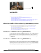
CH A P T E R 1 Functionality This section describes the following topics: • About Cisco Unified Videoconferencing 3500 Gateway Products, page 1-1 • About Gateway Features, page 1-2 • About Cisco Unified Videoconferencing 3500 Gateway Applications and Topologies, page 1-6 • About Cisco Unified Videoconferencing 3500 Gateway Functionality, page 1-10 About Cisco Unified Videoconferencing 3500 Gateway Products The Cisco Unified Videoconferencing 3500 Gateway series consists of the following products:
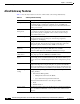
Chapter 1 Functionality About Gateway Features About Gateway Features Table 1-1 lists the major features of the Cisco Unified Videoconferencing 3500 Gateway. Table 1-1 Gateway Feature Summary Feature Description Interoperability The gateway provides a high degree of interoperability with other H.323 compliant gateways, gatekeepers, terminals, proxy, and Multipoint Control Unit (MCU) products by being based on the H.320 standard and H.323 protocol stack.
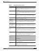
Chapter 1 Functionality About Gateway Features Table 1-1 Gateway Feature Summary (continued) Feature Description DTMF translation The gateway supports translation between in-band Dual Tone Multi-Frequency (DTMF) signals (on the ISDN side) and out-of-band H.245 messages (on the IP side). DTMF translation occurs for voice and video calls. Dual video The gateway supports H.239 standards-based dual video and TANDBERG DuoVideo technology.
Chapter 1 Functionality About Gateway Features Table 1-1 Gateway Feature Summary (continued) Feature Description Peer-to-peer connectivity The gateway supports connectivity to the IP network through a gatekeeper, or directly to a peer device such as Cisco Unified Communications Manager. IP network connections The gateway has one 10/100Base-T Ethernet IP port (on the front panel) and connects to an IP segment through a direct connection to a network switch.
Chapter 1 Functionality About Gateway Features Table 1-2 Cisco Gateway Feature Specifics (continued) Feature Cisco Unified Videoconferencing 3527 PRI Gateway Cisco Unified Videoconferencing 3522 BRI Gateway Call handling capabilities For 1 x PRI T1 line: For 4 x BRI lines: 23 ports (voice) 8 voice-only calls or 8 video calls or any combination of the two: 23 ports 1B (video and data) 11 ports 2B (video and data) 3 ports 6B (video and data) For 1 x PRI E1 line: 30 ports (voice) 30 ports 1B (video
Chapter 1 Functionality About Cisco Unified Videoconferencing 3500 Gateway Applications and Topologies Table 1-2 Cisco Gateway Feature Specifics (continued) Feature Cisco Unified Videoconferencing 3527 PRI Gateway Bonding calls Internal Imux providing calls at 128 Internal Imux providing calls at 128 Kbps (2B) up to 512 Kbps (8B) using Kbps (2B) up to full PRI of 1472 Kbps (23B) for T1 and up to full bonding mode 1. PRI of 1920 Kbps (30B) for E1 using bonding mode 1.
Chapter 1 Functionality About Cisco Unified Videoconferencing 3500 Gateway Applications and Topologies Figure 1-1 Multimedia Conferencing through the Gateway H.323 endpoint IP network Regular phone ISDN ISDN phone Cisco chassis/unit with serial gateway 157174 H.323 endpoint PSDN H.
Chapter 1 Functionality About Cisco Unified Videoconferencing 3500 Gateway Applications and Topologies About Multipoint Conferencing Together with the Cisco MCU, the Cisco PRI gateway and BRI gateway enable H.320 ISDN terminals to participate in a mixed ISDN-IP multipoint multimedia conference with IP network endpoints (see Figure 1-3). For example, when an H.320 ISDN terminal wants to participate in a multipoint conference with H.323 IP endpoints, the H.
Chapter 1 Functionality About Cisco Unified Videoconferencing 3500 Gateway Applications and Topologies The Cisco PRI gateway features configurable E1/T1 PRI ISDN connections. When configured as an E1 connection, each port provides 30 B channels and one D signaling channel. When configured as a T1 connection, each port provides 23 B channels and one D signaling channel. The type of line available depends on your local ISDN provider. You configure the gateway PRI port to an E1 or T1 interface accordingly.
Chapter 1 Functionality About Cisco Unified Videoconferencing 3500 Gateway Functionality BRI Gateways You can connect the BRI gateway to a local private branch exchange (PBX) that provides the BRI connection (as shown in Figure 1-6), or to a public phone network using an NT1 device (as shown in Figure 1-7). Figure 1-6 Connecting the BRI Gateway Directly to a PBX that Provides a BRI Line Private Public H.
Chapter 1 Functionality About Cisco Unified Videoconferencing 3500 Gateway Functionality About PRI Gateway Call Handling Capacity Table 1-3 lists the maximum call handling capacity of the PRI gateway for different types of calls.
Chapter 1 Functionality About Cisco Unified Videoconferencing 3500 Gateway Functionality Resource Allocation across E1/T1 Lines The gateway can allocate bandwidth resources to calls across separate E1 or T1 connections to maximize bandwidth capacity in cases where there is not enough capacity for a call on a single E1 or T1 connection, but where sufficient capacity does exist when remaining capacity on both E1/T1 lines is combined.
CH A P T E R 2 Setting Up Your Cisco Unified Videoconferencing 3500 Gateway This section describes the following topics: • Physical Description, page 2-1 • Preparing for Installation of the Cisco Cisco Unified Videoconferencing 3527 PRI Gateway, page 2-3 • Preparing for Installation of the Cisco Unified Videoconferencing 3522 BRI Gateway, page 2-4 • Verifying the Package Contents, page 2-5 • Mounting the Cisco Unified Videoconferencing 3500 Gateway Unit in a 19-inch Rack, page 2-5 • Cisco Unifi
Chapter 2 Setting Up Your Cisco Unified Videoconferencing 3500 Gateway Physical Description Table 2-1 Front Panel Components Component Description 10/100 BaseT connector An RJ-45 connector that provides the primary Ethernet connection for the IP network port. SERIAL connector A DB-9 connector that allows you to connect a PC terminal for local configuration. RST button Allows you to reset the Cisco Unified Videoconferencing 3500 Gateway unit manually.
Chapter 2 Setting Up Your Cisco Unified Videoconferencing 3500 Gateway Preparing for Installation of the Cisco Cisco Unified Videoconferencing 3527 PRI Gateway Table 2-2 Cisco Unified Videoconferencing 3527 PRI Gateway Rear Panel Components Component Description ALARM LED Displays alarm events for the PRI line. PRI LINE connector • YELLOW —Lights yellow when there is a loss of frame alignment at the remote side. • ORANGE—Lights orange when there is a loss of frame alignment in the gateway.
Chapter 2 Preparing for Installation of the Cisco Unified Videoconferencing 3522 BRI Gateway Setting Up Your Cisco Unified Videoconferencing 3500 Gateway • For an H.323 environment, the IP address of the H.
Chapter 2 Setting Up Your Cisco Unified Videoconferencing 3500 Gateway Verifying the Package Contents • Key Hold • ACO Verifying the Package Contents Inspect the contents of the box for shipping damage. Report any damage or missing items to your Cisco representative. Table 2-4 lists the package contents for the Cisco Unified Videoconferencing 3500 Gateway unit.
Chapter 2 Setting Up Your Cisco Unified Videoconferencing 3500 Gateway Cisco Unified Videoconferencing 3500 Gateway Unit Initial Configuration Fitting a Bracket for Rack Mounting 157263 Figure 2-4 Step 4 Pass the screws through the brackets and tighten them into the screw holes on each side of the Cisco Unified Videoconferencing 3500 Gateway unit using a suitable screwdriver. Step 5 Insert the Cisco Unified Videoconferencing 3500 Gateway unit into the 19-inch rack.
Chapter 2 Setting Up Your Cisco Unified Videoconferencing 3500 Gateway Cisco Unified Videoconferencing 3500 Gateway Unit Initial Configuration Connecting to a PC This section describes how to use the serial port connection to configure the Cisco Unified Videoconferencing 3500 Gateway unit with an IP address. Procedure Step 1 Locate the terminal cable shipped with the Cisco Unified Videoconferencing 3500 Gateway unit. Step 2 Connect the end labeled PC to the serial port on the computer.
Chapter 2 Setting Up Your Cisco Unified Videoconferencing 3500 Gateway Cisco Unified Videoconferencing 3500 Gateway Unit Initial Configuration Procedure Step 1 Connect the supplied terminal cable to the PC terminal. Step 2 Connect the power cable. Step 3 Start the terminal emulation application on the PC.
Chapter 2 Setting Up Your Cisco Unified Videoconferencing 3500 Gateway Cisco Unified Videoconferencing 3500 Gateway Unit Initial Configuration • Convert the subnet mask IP address to hexadecimal notation, type the hexadecimal number at the prompt, and press Enter. For example, for the subnet mask 255.255.255.0 the hexadecimal value you type is FFFFFF00. Note • You can use the computer’s desktop calculator to convert the subnet mask ID to hexadecimal notation. If a subnet mask is not used, press Enter.
Chapter 2 Connecting the Cisco Unified Videoconferencing 3500 Gateway Unit to the LAN Setting Up Your Cisco Unified Videoconferencing 3500 Gateway Connecting the Cisco Unified Videoconferencing 3500 Gateway Unit to the LAN This section describes how to connect the Cisco Unified Videoconferencing 3500 Gateway unit to the Local Area Network (LAN).
Chapter 2 Setting Up Your Cisco Unified Videoconferencing 3500 Gateway Accessing the Cisco Unified Videoconferencing 3500 Gateway Administrator Interface SVGA Port The Cisco Unified Videoconferencing 3500 Gateway unit is equipped with an SVGA port for connecting to a standard PC monitor screen. The SVGA port allows you to view the operating system desktop and to monitor the applications that are active on the desktop.
Chapter 2 Setting Up Your Cisco Unified Videoconferencing 3500 Gateway Registering the Online Help Procedure Step 1 Launch your browser and type the IP address or the name of the Cisco Unified Videoconferencing 3500 Gateway unit. For example, http://125.221.23.44 or board_name. The Cisco Unified Videoconferencing 3500 Gateway login page appears. Step 2 Type the Administrator user name and password in the appropriate fields and click Login. The default global user name is admin.
CH A P T E R 3 Using the Cisco Software Upgrade Utility This section describes the following topics: • Introduction, page 3-1 • Launching the Cisco Software Upgrade Utility, page 3-1 • Upgrading Software, page 3-2 Introduction The Cisco Software Upgrade Utility is an interactive GUI interface that enables you to upgrade Cisco software installed on Cisco devices. The Cisco Software Upgrade Utility enables you to select files to be uploaded via a network or modem connection to the Cisco device.
Chapter 3 Using the Cisco Software Upgrade Utility Upgrading Software Upgrading Software This section describes how to use the Software Upgrade Utility to upgrade Cisco software installed on Cisco devices. Procedure Step 1 In the General Information section of the Upgrade Utility dialog box, enter the IP address of the device you want to upgrade.
CH A P T E R 4 Cable Connections and Pin-outs This section describes the following topics: • Unit RS-232 9-Pin Serial Port, page 4-1 • RJ-45 8-Pin IP Network Port, page 4-2 • ISDN Port, page 4-2 Unit RS-232 9-Pin Serial Port Table 4-1 describes the Cisco Unified Videoconferencing 3500 Gateway unit RS-232 9-pin D-type serial port pin-out configuration.
Chapter 4 Cable Connections and Pin-outs RJ-45 8-Pin IP Network Port RJ-45 8-Pin IP Network Port Table 4-2 describes the pin-out configuration of the RJ-45 IP network port. Table 4-2 Pin-out Configuration of the RJ-45 IP Network Port Pin Function I/O 1 TXD+ Output 2 TXD+ Output 3 RXD+ Input 4 NC 5 NC 6 RXD- 7 NC 8 NC Input ISDN Port Table 4-3 describes the ISDN Port RJ-45 connector pin-out configuration.
CH A P T E R 5 Technical Specifications This section provides technical specifications for the Cisco Unified Videoconferencing 3500 Gateway Technical Specifications Table Table 5-1 Cisco Unified Videoconferencing 3500 Gateway Unit Technical Specifications Unit Dimensions • Height: 1U (1.75 inches or 44.45 mm) • Width: 17.25 inches (438.15 mm) • Depth: 10 inches (254 mm) • Weight: 4.45 kg (9.
Chapter 5 Technical Specifications Technical Specifications Table Table 5-1 Cisco Unified Videoconferencing 3500 Gateway Unit Technical Specifications Communication Interfaces Front panel Rear panel (Cisco Unified Videoconferencing 3527 PRI Gateway) • Ethernet 10/100 Mbps auto-negotiate speed select • Asynchronous serial port RS-232 connected via 9-pin D-type connector • RJ-45 serial port (for video processing module) • SVGA port (for video processing module) • USB connector (for video proce
Chapter 5 Technical Specifications Technical Specifications Table Installation and Upgrade Guide for Cisco Unified Videoconferencing 3522 BRI Gateway and 3527 PRI Gateway Release 5.
Chapter 5 Technical Specifications Technical Specifications Table Installation and Upgrade Guide for Cisco Unified Videoconferencing 3522 BRI Gateway and 3527 PRI Gateway Release 5.
CH A P T E R 6 Safety This section describes the following topics: • Electrical Safety, page 6-1 • ESD Procedures, page 6-2 Electrical Safety To avoid an electric shock or damage to the Cisco Unified Videoconferencing 3500 Gateway unit, servicing should be performed by qualified service personnel only. To reduce the risk of damaging power surges, Cisco recommends installing an AC surge arrestor in the AC outlet from which the Cisco Unified Videoconferencing 3500 Gateway unit is powered.
Chapter 6 Safety ESD Procedures Caution This is a class I unit. In Denmark, use this unit with an AC cord suited to Danish specifications. The cord should include an earthing conductor. Plug the unit into a wall socket outlet which is connected to the protective earth contact. Do not use socket outlets which are not connected to a protective earth contact! Laite on liitettävä suojamaadoituskoskettimilla varustettuun pistorasiaan. Apparatet må tilkoples jordet stikkontakt.
Chapter 6 Sicherheit Elektrische Sicherheit Sicherheit Dieses Kapitel beschreibt die Sicherheitsvorschriften und -vorgaben zur Bedienung der Cisco Unified Videoconferencing 3515-Plattform einschließlich des Folgenden: • Elektrische Sicherheit, page 6-3 • ESD-Verfahren, page 6-3 • Warnhinweise, page 6-3 Elektrische Sicherheit Zur Vermeidung eines elektrischen Schlags oder Schäden an der Cisco Unified Videoconferencing 3515-Plattform darf die Wartung von qualifiziertem Fachpersonal vorgenommen werden.
Chapter 6 Seguridad Seguridad Electrica Seguridad Seguridad Electrica Para evitar una sacudida eléctrica o daños en la unidad Cisco Unified Videoconferencing 3515, las reparaciones deberán ser realizadas sólo por personal técnico calificado. Para reducir el riesgo de las sobretensiones, Cisco recomienda instalar un protector contra sobretensiones de CA en la salida de CA que alimenta a la unidad Cisco Unified Videoconferencing 3515. • No intente abrir la unidad Cisco Unified Videoconferencing 3515.
Chapter 6 Seguridad Procedimientos ESD Procedimientos ESD Para evitar daños a la unidad Cisco Unified Videoconferencing 3515 por descarga electrostática (ESD) aleatoria, se recomienda utilizar muñequeras antiestática. Installation and Upgrade Guide for Cisco Unified Videoconferencing 3522 BRI Gateway and 3527 PRI Gateway Release 5.
Chapter 6 Securite Securite Electrique Securite Cette section décrit les procédures et les exigences en matière de sécurité concernant la mise en exploitation de la Cisco Unified Videoconferencing 3515.
Chapter 6 Securite Prevention des Decharges Electrostatiques Haute Tension Débranchez l’unité Cisco Unified Videoconferencing 3515 de la prise électrique avant d’enlever le couvercle. Évitez toute intervention, opération d’entretien ou réparation sur un châssis ouvert sous tension. Ces actions ne devraient être effectuées que par une personne expérimentée et connaissant les dangers encourus.
Chapter 6 Securite Prevention des Decharges Electrostatiques Installation and Upgrade Guide for Cisco Unified Videoconferencing 3522 BRI Gateway and 3527 PRI Gateway Release 5.
CH A P T E R 7 Compliance and Certifications This section describes the following topics: • Safety Compliance, page 7-1 • EMC, page 7-2 • Telecom, page 7-2 • Environmental Compliance, page 7-4 Safety Compliance This section lists the safety standards supported by the Cisco Unified Videoconferencing 3500 Gateway unit. • UL 60950 • CSA C22.2 No.
Chapter 7 Compliance and Certifications EMC EMC This section lists the EMC compliance for the Cisco Unified Videoconferencing 3500 Gateway unit. Warning • FCC Part 15 (CFR 47) Class A • ICES-003 Class A • EN 55022 Class A • CISPR22 Class A • AS/NZS CISPR22 Class A • VCCI Class A • CISPR24 • EN 55024 • EN 50082-1 • EN 61000-3-2 • EN 61000-3-3 • EN 61000-6-1 This is a class A product.
Chapter 7 Compliance and Certifications Telecom ACTA Part 68 Notice Step 1 This equipment complies with ACTA Part 68. On the cover of this equipment is a label that contains, among other information, the ACTA registration number. If requested, this information must be provided to the telephone company. Step 2 Applicable registration jack USOCs (Universal Service Order Codes) for the equipment is RJ48C for PRI interfaces and RJ49C for BRI interfaces.
Chapter 7 Compliance and Certifications Environmental Compliance The abbreviation, IC, before the registration number signifies that registration was performed based on a Declaration of Conformity indicating that Industry Canada technical specifications were met. It does not imply that Industry Canada approved the equipment. Warning Users should not attempt to make such connections themselves, but should contact the appropriate electric inspection authority, or electrician, as appropriate.
I N D EX call bandwidth overhead A 1-11 call handling access control ACT LED 1-2 BRI gateway capacity 2-2, 2-3 capabilities Administrator interface ALRM LED 2-2, 2-3 audio codecs 1-4 audio transcoding auto-boot 2-11 1-11 1-5 PRI gateway capacity 1-11 Certifications EMC 1-4 7-2 Telecom 2-6 chipset 7-2 5-2 communication interfaces conceal caller ID B 5-2 1-3 connectors bandwidth call overhead 1-11 resource allocation supported 1-12 BRI line 2-3 Ethernet 2-2 PRI line 2-
Index ISDN E connection failure E1/T1 EMC 1-9, 1-12 rollover 7-2 IVR encryption 1-3 1-3 1-3 1-2 internal capacity 1-6 Ethernet 10/100Base-T connector 2-2 Ethernet LED 2-2 1-5 L LAN 2-2, 2-10 10/100Base-T LED indicators F line quality failsafe 5-2 fast start 2-2, 2-3, 5-1 1-5 local 1-3 configuration feature summary monitoring general features specific 2-10 2-10 1-2 1-4 first-time installation front panel 1-5 M 2-11 2-1 memory MSN 5-2 1-2 multimedia conferencing
Index default login user RJ-45 2-9 peer-to-peer 2-2, 2-3, 2-10 rollover connectivity routing 1-4, 1-12 physical description gateway 1-3 1-2 RS-232 DTE 9-pin D-type connection 2-1 pin-out configuration RST button RJ-45 IP network port 1-5 2-2, 5-1 4-2 RS-232 9-pin D-type serial port point-to-point conferencing 4-1 1-7 ports S Safety RJ-45 IP 4-2 compliance RS-232 9-pin serial SVGA 4-1 electrical 2-11 power supply Prevention 6-1 ESD procedures 5-2 serial control port 6-7
Index TCS4 1-2 Telecom 7-2 U unit dimensions upgrade software 5-1 3-1 V video conferencing protocols video protocols video resolutions 1-4 1-4 1-4 W web-based management 1-2 Installation and Upgrade Guide for Cisco Unified Videoconferencing 3522 BRI Gateway and 3527 PRI Gateway Release 5.