Quick Start Guide Cisco 2800 Series Integrated Services Routers Quick Start Guide INCLUDING LICENSE AND WARRANTY 1 Cisco 90-Day Limited Hardware Warranty Terms 2 Overview 3 Documents, Equipment, and Tools 4 Install Chassis 5 Connect Cables 6 Power Up the Router 7 Interface Numbering 8 Perform Initial Configuration 9 Where to Go Next 10 Obtaining Documentation 11 Documentation Feedback 12 Cisco Product Security Overview 13 Obtaining Technical Assistance 14 Obtaining Additional Publications
Revised: October 11, 2005, 78-16015-07 1 Cisco 90-Day Limited Hardware Warranty Terms There are special terms applicable to your hardware warranty and various services that you can use during the warranty period. Your formal Warranty Statement, including the warranties and license agreements applicable to Cisco software, is available on Cisco.com. Follow these steps to access and download the Cisco Information Packet and your warranty and license agreements from Cisco.com. 1.
To Receive a Return Materials Authorization (RMA) Number Contact the company from whom you purchased the product. If you purchased the product directly from Cisco, contact your Cisco Sales and Service Representative.
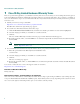
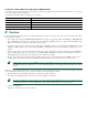
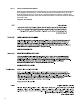
Product Serial Number Location You may need your product serial number when calling the Technical Assistance Center (TAC). Figure 1 shows the serial number location for the Cisco 2801 router. The label is located on the rear of the chassis, at the bottom edge, near the lower left corner. Figure 1 Serial Number Label Location for Cisco 2801 Router 271410 SN: AAANNN NXXXX SN: AAANNNNXXXX Figure 2 shows the serial number location for the Cisco 2811 router.
Cisco Product Identification Tool The Cisco Product Identification (CPI) tool provides detailed illustrations and descriptions showing where to find serial number labels on Cisco products.
Items Included with Cisco 2811, Cisco 2821, and Cisco 2851 Routers Your router package should include the following items in addition to the router: • RJ-45-to-DB-9 console cable and RJ-45-to-DB-25 modem cable for management access • Ground lug; AC power cord with AC-powered routers • Cisco product registration card; Cisco.
Warning Definition Warning IMPORTANT SAFETY INSTRUCTIONS This warning symbol means danger. You are in a situation that could cause bodily injury. Before you work on any equipment, be aware of the hazards involved with electrical circuitry and be familiar with standard practices for preventing accidents. Use the statement number provided at the end of each warning to locate its translation in the translated safety warnings that accompanied this device.
Avvertenza IMPORTANTI ISTRUZIONI SULLA SICUREZZA Questo simbolo di avvertenza indica un pericolo. La situazione potrebbe causare infortuni alle persone. Prima di intervenire su qualsiasi apparecchiatura, occorre essere al corrente dei pericoli relativi ai circuiti elettrici e conoscere le procedure standard per la prevenzione di incidenti. Per le traduzioni delle avvertenze riportate in questo documento, vedere le avvertenze di sicurezza che accompagnano questo dispositivo.
Aviso INSTRUÇÕES IMPORTANTES DE SEGURANÇA Este símbolo de aviso significa perigo. Você se encontra em uma situação em que há risco de lesões corporais. Antes de trabalhar com qualquer equipamento, esteja ciente dos riscos que envolvem os circuitos elétricos e familiarize-se com as práticas padrão de prevenção de acidentes. Use o número da declaração fornecido ao final de cada aviso para localizar sua tradução nos avisos de segurança traduzidos que acompanham o dispositivo.
Advarsel VIGTIGE SIKKERHEDSANVISNINGER Dette advarselssymbol betyder fare. Du befinder dig i en situation med risiko for legemesbeskadigelse. Før du begynder arbejde på udstyr, skal du være opmærksom på de involverede risici, der er ved elektriske kredsløb, og du skal sætte dig ind i standardprocedurer til undgåelse af ulykker. Brug erklæringsnummeret efter hver advarsel for at finde oversættelsen i de oversatte advarsler, der fulgte med denne enhed.
Warning Before working on a system that has an on/off switch, turn OFF the power and unplug the power cord. Statement 1 Warning Read the installation instructions before connecting the system to the power source. Statement 1004 Warning This unit is intended for installation in restricted access areas. A restricted access area can be accessed only through the use of a special tool, lock and key, or other means of security.
Warning Only trained and qualified personnel should be allowed to install, replace, or service this equipment. Statement 1030 Warning To prevent personal injury or damage to the chassis, never attempt to lift or tilt the chassis using the handles on modules (such as power supplies, fans, or cards); these types of handles are not designed to support the weight of the unit. Statement 1032 Warning This equipment must be installed and maintained by service personnel as defined by AS/NZS 3260.
Rack-Mounting the Router Cisco 2811, Cisco 2821, and Cisco 2851 routers can be installed in 19- and 23-inch (48.26-cm and 58.42-cm) racks. Cisco 2801 routers can be installed only in 19-inch racks, and cannot be center mounted. Use the standard brackets for mounting the chassis in a 19-inch rack; use the optional larger brackets for mounting the chassis in a 23-inch rack.
Attach the second bracket to the opposite side of the chassis. Use a number 2 Phillips screwdriver to install the bracket screws. Caution Your chassis installation must allow unrestricted airflow for chassis cooling. Figure 7 Bracket Installation for Front Mounting SYS AUX/ PWR PWR SYS ACT CF COMPACT FLASH Do Not Remov e During OPTIONAL 12V Network CONSOLE 1 0 Operation AUX RPS INPUT 18A 100-240 V~ 3A 50/60 Hz Bracket for 23-inch rack Bracket for 19-inch rack Use four screws on each side.
Installing the Router in a Rack Warning To prevent bodily injury when mounting or servicing this unit in a rack, you must take special precautions to ensure that the system remains stable. The following guidelines are provided to ensure your safety: • This unit should be mounted at the bottom of the rack if it is the only unit in the rack. • When mounting this unit in a partially filled rack, load the rack from the bottom to the top with the heaviest component at the bottom of the rack.
Figure 11 Attaching the Cable Management Bracket to the Cisco 2811 Router S L O T 3 S L O T 1 S L O T 2 A F A= ACT S= SPEE D FE 0/1 A= FDX A= LINK FE 0/0 A S S L O L T 0 95947 ENM0 F S L PVDM1 PVDM0 AIM1 AIM0 Cable management bracket. Either edge may go up. Attach to either side of the chassis. Wall-Mounting the Router—Cisco 2811 Routers Only You can mount a Cisco 2811 router on a wall. Cisco 2801, Cisco 2821, and Cisco 2851 routers are not designed for wall-mounting.
Caution The router must be mounted with the power connections oriented downward. Failure to do so could present a fire hazard. Installing the Router on a Desktop If you install your Cisco 2800 series router on a desktop, observe the following precautions: Note For Cisco 2801 routers, attach the four rubber feet to the bottom of the chassis. Caution Your chassis installation must allow unrestricted airflow for chassis cooling. For placing the router on a desktop, keep at least 1 inch (2.
Step 2 Crimp the ground wire to the ground lug or ring terminal, using a crimp tool of the appropriate size. Step 3 Attach the ground lug or ring terminal to the chassis as shown in Figure 13, Figure 14, Figure 15, Figure 16, or Figure 17. For a ground lug, use the two screws with captive locking washers provided. For a ring terminal, use one of the screws provided. Tighten the screws to a torque of 8 to 10 in-lb (0.9 to 1.1 N-m).
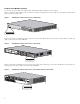
Figure 16 A F A= ACT S= SPEE D FE 0/1 NEBS-Compliant Chassis Ground Connection on Cisco 2821 or Cisco 2851 Chassis A= FDX A= LINK FE 0/0 A S F L S L AIM0 98807 PVDM2 PVDM1 PVDM0 AIM1 Ground lug Figure 17 A F A= ACT S= SPEE D FE 0/1 Chassis Ground Connection Using Ring Terminal on Cisco 2821 or Cisco 2851 Chassis A= FDX A= LINK FE 0/0 A S F L S L AIM0 103065 PVDM2 PVDM1 PVDM0 AIM1 Ring terminal attachment 5 Connect Cables Warning Only trained and qualified personnel should be allowed
Caution To comply with Telcordia NEBS GR-1089-Core and EN 300386 requirements, you must use foil twisted-pair cable that is properly grounded at both ends. Power Connections This section describes procedures for connecting your router to AC power, DC power, and backup power.
Connecting the Router to DC Power If your router has a DC-input power supply, follow the directions in this section for proper wiring. If backup power is required, see the “Connecting the Router to Backup Power” section on page 26. Note Cisco 2801 routers are not designed to connect to DC power. DC Wiring Requirements for Cisco 2800 Series Routers Caution DC return is isolated from the frame (NEBS DC-I).
Wiring Procedure for DC Input To connect the router to a DC power source, perform the following steps: Step 1 Remove power from the DC circuit. To ensure that power is removed from the DC circuit, locate the circuit breaker for the DC circuit, switch the circuit breaker to the OFF position, and tape the circuit-breaker switch in the OFF position. Warning Before performing any of the following procedures, ensure that power is removed from the DC circuit.
Step 6 Install the plastic covers over the terminals. (See Figure 19 or Figure 20.) Warning The safety cover is an integral part of the product. Do not operate the unit without the safety cover installed. Operating the unit without the cover in place will invalidate the safety approvals and pose a risk of fire and electrical hazards. Statement 117 Step 7 Organize and secure the wires using cable ties as shown in Figure 19 or Figure 20.
Approved Scenarios and Scenarios Not Approved for Dual DC Power Supply Configuration You can connect a single DC power source to either the A input or the B input. If there are dual power sources, connect one source to the A input and one source to the B input. Both sources must be the same polarity (with respect to ground) and voltage (within 0.25 volts). Do not connect –DC grounded and +DC grounded dual sources to Cisco 2811, Cisco 2821, and Cisco 2851 series integrated services routers.
Note When source A and source B are wired with common negative terminals, as in Figure 22, discharging does not occur and there is no restriction requiring that source A and source B voltages be equal. Figure 23 Connecting Source A and Source B with Common Positive Terminals Va voltage = Vb voltage (greater than 0.25 V) Va voltage = Vb voltage (within 0.25 V) AVa + A+ + Va A+ + B+ Vb B+ Vb B- B- 127040 + A- In Figure 24, source A and source B are wired with opposite polarity grounds.
Connecting the Router to Backup Power If your router uses the Cisco Redundant Power System (RPS), see the Cisco RPS-675 Hardware Installation Guide for instructions about the power connections. To locate this document, see the “Where to Go Next” section on page 36. Caution Note Before connecting the RPS to the router, make sure that either the RPS is in standby mode or the RPS AC power is disconnected. Connecting the RPS to AC power automatically places the RPS in active mode.
Table 3 summarizes some typical WAN, LAN, and voice connections for the Cisco 2800 series routers.
System Management Connections The connections described in Table 4 provide system management access.
Power-Up Procedure To power up your Cisco 2800 series router and verify that it goes through its initialization and self-test, perform this procedure. When the procedure is finished, the Cisco 2800 series router is ready to configure. Note To view the boot sequence, you must have a console connection to the Cisco 2800 series router before it powers up. Step 1 Make sure that your PC is powered up and connected as described in the “Checklist for Power-Up” section on page 28.
Verify the Front Panel LED Indications The indicator LEDs described in Table 5 provide power, activity, and status information: Table 5 LED Indicators on Front Panel LED Label LED Color or State Meaning SYS PWR Solid green System is operating normally. Blinking green System is booting or is in ROM monitor mode. Amber System error. Off Power is off. Green IP phone power is operating normally (if installed) or Cisco Redundant Power System (RPS) is operating normally (if installed).
Table 6 Interface Numbering on Cisco 2801 Series Routers Slot Number Slot Type Interface Numbering Range Onboard ports Fast Ethernet 0/0 and 0/1 0 VIC/VWIC (voice only—no PRI support) 0/0/0 to 0/0/3 1 HWIC/WIC/VIC/VWIC1 0/1/0 to 0/1/3 (single-wide HWIC) 0/1/0 to 0/1/8 (double-wide HWIC) 2 WIC/VIC/VWIC 3 1 HWIC/WIC/VIC/VWIC 0/2/0 to 0/2/3 1 0/3/0 to 0/3/3 (single-wide HWIC) 0/3/0 to 0/3/8 (double-wide HWIC) 1.
1. 2. 3. 4. 5. 6. 7. Interface abbreviations: fa = Fast Ethernet; gi = Gigabit Ethernet; usb = Universal Serial Bus; bri = ISDN basic rate interface. The interfaces listed are examples only; other possible interface types are not listed. Interface card slot numbers for double (HWIC-D) slots are 1 and 3 only. Specify the line number in the Cisco IOS CLI by using the interface number for the associated asynchronous serial interface. “1” is the network module slot number in all Cisco 2800 series routers.
Initial Configuration Using the Setup Command Facility This section shows how to use the setup command facility to configure a hostname for the router, set passwords, and configure an interface for communication with the management network. If the following messages appear at the end of the startup sequence, the setup command facility has been invoked automatically: --- System Configuration Dialog --At any point you may enter a question mark '?' for help.
Step 6 Enter the virtual terminal password, which prevents unauthenticated access to the router through ports other than the console port: The virtual terminal password is used to protect access to the router over a network interface.
interface FastEthernet0/1 shutdown no ip address ! end Step 11 Respond to the following prompts. Choose [2] to save the initial configuration: [0] Go to the IOS command prompt without saving this config. [1] Return back to the setup without saving this config. [2] Save this configuration to nvram and exit. Enter your selection [2]: 2 Building configuration... Use the enabled mode 'configure' command to modify this configuration.
Step 4 Enter privileged EXEC mode: Router> enable Router# Step 5 For configuration procedures, see the applicable configuration instructions in the Cisco 2800 series software configuration documents. See the “Where to Go Next” section on page 36 for information about accessing these documents. Note Step 6 To avoid losing work you have completed, be sure to save your configuration occasionally as you proceed. Use the copy running-config startup-config command to save the configuration to NVRAM.
10 Obtaining Documentation Cisco documentation and additional literature are available on Cisco.com. Cisco also provides several ways to obtain technical assistance and other technical resources. These sections explain how to obtain technical information from Cisco Systems. Cisco.com You can access the most current Cisco documentation at this URL: http://www.cisco.com/techsupport You can access the Cisco website at this URL: http://www.cisco.
11 Documentation Feedback You can rate and provide feedback about Cisco technical documents by completing the online feedback form that appears with the technical documents on Cisco.com. You can send comments about Cisco documentation to bug-doc@cisco.com.
13 Obtaining Technical Assistance Cisco Technical Support provides 24-hour-a-day award-winning technical assistance. The Cisco Technical Support & Documentation website on Cisco.com features extensive online support resources. In addition, if you have a valid Cisco service contract, Cisco Technical Assistance Center (TAC) engineers provide telephone support. If you do not have a valid Cisco service contract, contact your reseller.
Severity 3 (S3)—Operational performance of your network is impaired, but most business operations remain functional. You and Cisco will commit resources during normal business hours to restore service to satisfactory levels. Severity 4 (S4)—You require information or assistance with Cisco product capabilities, installation, or configuration. There is little or no effect on your business operations.
Corporate Headquarters Cisco Systems, Inc. 170 West Tasman Drive San Jose, CA 95134-1706 USA www.cisco.com Tel: 408 526-4000 800 553-NETS (6387) Fax: 408 526-4100 European Headquarters Cisco Systems International BV Haarlerbergpark Haarlerbergweg 13-19 1101 CH Amsterdam The Netherlands www-europe.cisco.com Tel: 31 0 20 357 1000 Fax: 31 0 20 357 1100 Americas Headquarters Cisco Systems, Inc. 170 West Tasman Drive San Jose, CA 95134-1706 USA www.cisco.