
User Guide
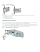
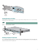
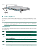
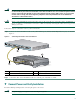
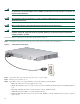
Table Of Contents
- Cisco 1760 Modular Access Router Cabling and Installation
- 1 Cisco One-Year Limited Hardware Warranty Terms
- 2 Overview
- 3 Parts List
- 4 Mounting the Router in a Rack
- 5 Installing WIC/VIC Cards
- 6 Connecting the Router to Your Local Network
- 7 Connect Power and Verify Installation
- 8 Connect a PC to the Router Console Port
- 9 Perform Initial Configuration
- 10 Use the CLI to Configure VoIP
- 11 Obtaining Documentation
- 12 Documentation Feedback
- 13 Cisco Product Security Overview
- 14 Obtaining Technical Assistance
- 15 Obtaining Additional Publications and Information
5
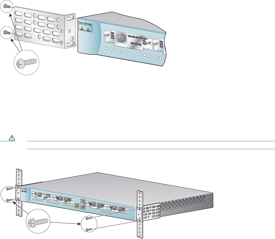
Attaching Brackets to the Rack
After the brackets are attached to the router, use the four supplied number-12 Phillips machine screws to securely attach the
brackets to the rack, as shown in Figure 3.
Caution Make sure that the fans on the side of the chassis are not blocked.
Figure 3 Attaching Brackets to the Rack
Attaching the Optional Cable Guide
Cisco recommends attaching the cable guide to prevent the cables from obscuring the front panel of the router and the other
devices installed in the rack. If the router is in a 19-inch or 24-inch rack, use the supplied black screw, as shown in Figure 4, to
attach the cable guide to the left or right bracket.
PVDM
0
O
K
O
K
PW
R
1
0
SLO
T 0
OK
PVDM
1
OK
MO
D
O
K
1
0
SLOT 1
O
K
Phillips
truss-head
screws
24" Configuration
60943
Cisco 1700
Series
10/100 ETHERNET
A
UX
C
ON
SOLE
PVDM 0
OK
OK
PWR
1
0
SLOT 0
OK
PVDM 1
OK
MOD
OK
1
0
SLOT 1
OK
LINK
100
FDX
ACT
COL
1
0
SLOT 2
OK
1
0
SLOT 3
OK
60941
Phillips machine screws