Quick Start Guide Cisco 1760 Modular Access Router Cabling and Installation INCLUDING LICENSE AND WARRANTY 1 Cisco One-Year Limited Hardware Warranty Terms 2 Overview 3 Parts List 4 Mounting the Router in a Rack 5 Installing WIC/VIC Cards 6 Connecting the Router to Your Local Network 7 Connect Power and Verify Installation 8 Connect a PC to the Router Console Port 9 Perform Initial Configuration 10 Use the CLI to Configure VoIP 11 Obtaining Documentation 12 Documentation Feedback 13 Cisco
1 Cisco One-Year Limited Hardware Warranty Terms There are special terms applicable to your hardware warranty and various services that you can use during the warranty period. Your formal Warranty Statement, including the warranties and license agreements applicable to Cisco software, is available on Cisco.com. Follow these steps to access and download the Cisco Information Packet and your warranty and license agreements from Cisco.com. 1. Launch your browser, and go to this URL: http://www.cisco.
Complete the information below, and keep it for reference. Company product purchased from Company telephone number Product model number Product serial number Maintenance contract number 2 Overview This document describes the hardware installation and software configuration steps necessary to install your Cisco 1760 modular access router with its complement of WAN interface cards (WICs) and voice interface cards (VICs). Additional documentation can be found on Cisco.com.
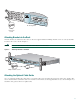
Figure 1 Bracket Mounting Points 24" rack mount point 19" rack mount point 24" rack mount point 38398 19" rack mount point To install the router in a 19-inch or a 24-inch standard rack, follow the instructions described in these procedures: • Attaching Brackets to the Router • Attaching Brackets to the Rack • Attaching the Optional Cable Guide Attaching Brackets to the Router The bracket orientation and the screws you use depend on whether you are attaching the brackets for a 19-inch or a 24-inch ra
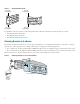
OK PVDM 0 PVDM 1 MOD OK OK OK SLOT 0 OK 24" Configuration 0 1 SLOT 1 OK 0 1 60943 PWR Phillips truss-head screws Attaching Brackets to the Rack After the brackets are attached to the router, use the four supplied number-12 Phillips machine screws to securely attach the brackets to the rack, as shown in Figure 3. Caution Make sure that the fans on the side of the chassis are not blocked.
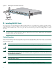
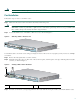
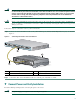
Figure 4 Attaching the Cable Guide to the Router CONSO LE OK PVDM 0 PVDM 1 MOD OK OK OK SLOT 0 OK 0 1 SLOT 1 OK 0 1 ACT COL FDX 100 LINK Cisco 170 10/100 ETHER NET AUX SLOT 2 OK 0 1 SLOT 3 OK 0 1 0 Series 65286 PWR Cable guide screw 5 Installing WIC/VIC Cards The router has four card slots that hold Cisco WICs and VICs. Either one or two WICs may be installed, with the remaining slots holding VICs, as desired. If no WICs are present in the slots, up to four VICs may be installed.
Do not connect a WAN, telephone or fax cable to the card until you have completed the installation procedure. Caution Card Installation Follow these steps to insert a card in the router: Make sure the router is turned off and is disconnected from AC power. Step 1 Power must be removed from the system prior to installing or removing WICs or VICs to avoid damaging them.
Slots 2 and 3 accept VICs only. These slots have a small metal tab on the right side that interferes with a similar tab on WICs, preventing the insertion of WICs by mistake. Note Step 6 Tighten the screws that are on the card.
Warning The ports labeled 10/100-Mbps Ethernet port and Console port are safety extra-low voltage (SELV) circuits. SELV circuits should only be connected to other SELV circuits. Because BRI circuits are treated like telephone-network voltage, avoid connecting the SELV circuits to the telephone network voltage (TNV) circuits. (To see translated versions of this warning, refer to the Regulatory Compliance and Safety Information for Cisco 1700 Routers document that came with the router.
Warning This product relies on the building’s installation for short-circuit (overcurrent) protection. Ensure that a fuse or circuit breaker no larger than 120VAC, 15A U.S. (240VAC, 16A international) is used on the phase conductors (all current-carrying conductors). Warning This equipment needs to be grounded. Use a green-and-yellow 14 AWG ground wire to connect the host to earth ground during normal use. Warning When installing the unit, always make the ground connection first and disconnect it last.
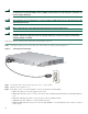
• MOD OK—On when the virtual private network (VPN) module is correctly installed in its slot and is recognized by the system. 8 Connect a PC to the Router Console Port Connect a PC to the router’s console port and establish a console session to view startup messages and verify voice card installation. Follow these steps to connect the router to a terminal or PC: Connect the light blue console cable to the blue console port on the router, as shown in Figure 10.
--- System Configuration Dialog --At any point you may enter a question mark '?' for help. Use ctrl-c to abort configuration dialog at any prompt. Default settings are in square brackets '[]'. Would you like to enter the initial configuration dialog? [yes/no]: To learn how to use the CLI to configure the router, see the “Initial Configuration Using Cisco CLI—Manual Configuration” section on page 12.
If these messages do not appear, SDM and a default configuration file were installed on the router at the factory. To use SDM to configure the router, see the “Initial Configuration Using Cisco Router and Security Device Manager” section on page 12. Note Be sure to save your configuration changes occasionally so that they are not lost during resets, power cycles, or power outages.
10 Use the CLI to Configure VoIP The following sections explain how to set up basic VoIP configurations using the Cisco IOS command line interface (CLI). Note VoIP requires one of the IP/Plus/Voice feature sets from IOS Release 12.2(2)XK, or later.
The router is now configured to start in the new configuration. Configuring the Fast Ethernet Interface To configure the Fast Ethernet interface, follow these steps, beginning in global configuration mode: Command Purpose Step 1 Router(config)# interface fastethernet 0/0 Enter configuration mode for the Fast Ethernet interface. Step 2 Router(config-if)# ip address 20.20.20.20 255.255.255.0 Set the IP address and subnet mask for the Fast Ethernet interface.
The destination-pattern command defines the telephone number associated with the VoFR dial peer. The session target command specifies a destination DLCI for the VoFR dial peer. Use the dial-peer voice command to define dial peers and to change to dial peer configuration mode. For examples, see the “Configuring FXS Interfaces” section on page 17, the “Configuring FXO Interfaces” section on page 23, and the “Configuring E&M Interfaces” section on page 24.
• An FXO (foreign exchange office) interface connects local calls to a PSTN central office or to a PBX that does not support E&M signaling. This is the interface a standard telephone provides. Ports on this VIC are pink. • An E&M is a signaling technique for two-wire and four-wire telephone and trunk interfaces. The E&M VIC connects remote calls from an IP network to a PBX for local distribution. Ports on this VIC are brown.
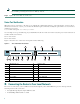
Table 2 West Router Telephone Numbers and Voice Ports Telephone Number Voice Port 408 555-3737 0/0 408 555-4141 0/1 Note If your router is configured with four 2-port VICs, you can connect a total of eight telephones and fax machines to it. As the router has only four slots, you need to replace one VIC with a WIC to provide an interface for IP connectivity to the WAN and for data traffic.
West(config)# These commands are summarized in Figure 13. Figure 13 West Router Configured for Local Dial Peers dial-peer voice 401 pots destination-pattern 14085553737 port 0/0 FXS VIC 0/0 FXS VIC 0/1 dial-peer voice 402 pots destination-pattern 14085554141 port 0/1 22635 IP cloud West The dial-peer command always takes the argument voice. The number following it is the dial-peer tag, and pots is the type of dial peer.
Table 4 East Router Local Dial Peers Telephone Number Destination Pattern Voice Port Dial-Peer Tag 919 555-8282 19195558282 1/0 901 919 555-9595 19195559595 1/1 902 Enter the following commands to configure the local ports on the East router with the dial-peer information in Table 4: East(config)# dial-peer East(config-dial-peer)# East(config-dial-peer)# East(config)# dial-peer East(config-dial-peer)# East(config-dial-peer)# East(config-dial-peer)# East(config)# voice 901 pots destination-pat
Figure 16 IP Connection Between Routers 408 555-3737 919 555-8282 FXS VIC 0/0 192.168.19.27 IP cloud 192.168.11.3 East FXS VIC 0/1 FXS VIC 1/1 919 555-9595 22335 408 555-4141 West FXS VIC 1/0 Look at the connection between the West router and the IP network. This connection does not include a voice port or an attached telephone—it leads from a WAN interface to a remote destination somewhere on the IP network.
You can simplify this process by configuring number expansion for East router telephone numbers on the West router: West(config)# num-exp 5.... 1919555.... Now users can dial a five-digit extension beginning with 5 from a telephone on the West router to reach a telephone on the East router. These commands are summarized in Figure 17. Figure 17 West Router Configured for Remote Dial Peers 192.168.11.
Checking the Remote Dial Peer Configuration If you configured VoIP dial peers on your router by following these examples, you can place calls from that router to telephones on the remote routers (using just the extension if you configured number expansion). If you have trouble placing calls, ping the remote router to make sure you have IP connectivity, or use the show dial-peer voice command to verify that the data you configured is correct.
Note In this example, West router voice port 1/0 has two separate POTS dial peers associated with it. Dial peer 201 matches calls beginning with the digit 9 and handles PSTN calls originating from the West router. Dial peer 601 matches calls beginning with the digit 7 and handles calls to the PSTN originating from the East router.
In this example, West users can dial 5 and a four-digit extension to reach telephones in the East office. East users can dial 5 and a four-digit extension to reach telephones in the West office. The West router connects to the PBX through an E&M VIC port 0/0. This port is associated with a POTS dial peer for incoming calls. But you no longer need to associate every telephone number with its own port.
Configure the East router similar to the West router. The East router connects to the PBX through an E&M VIC port 0/1. Enter the following commands to configure a POTS dial peer for all East telephones: East(config)# dial-peer voice 211 pots East(config-dial-peer)# destination-pattern 1919555....
Figure 22 A Network Using ISDN BRI Voice Interfaces Router A: Cisco 1760 Router B: Cisco 1760 WAN/IP Network BRI NT interface PSTN 60960 PBX BRI TE interface Configuring the BRI Layer 1 At the BRI Layer 1, you can configure each port of the VIC to operate in NT (clock source) or TE (clock slave) mode by using the IOS isdn layer1-emulate command in interface configuration mode: isdn layer1-emulate {network | user} where network enables the VIC to operate in the NT mode, and user enables it to operat
where high enables the external clock, and low enables the internal clock to drive the VIC. By default, the clock priority is set to high. Note If the VIC loses its external clock source, as when the ISDN line is down, the internal clock source takes over until the external clock is functioning again. Configuration Example To configure each BRI interface, follow these steps, starting in privileged user mode.
Debugging Commands Use the following commands to debug your configuration: • debug bri • debug isdn q921 • debug isdn q931 • debug isdn events • show isdn status bri • show controller bri • show interfaces bri For more information about these commands, see the IOS documentation. Configuring DID Interfaces Direct Inward Dialing (DID) enables external callers to direct-dial an internal extension on your PBX, without operator assistance.
Prerequisites The following actions are required to support DID: • Obtain DID service from your service provider. • Establish a working network. • Complete your company’s dial plan. • Establish a working telephony network based on your company’s dial plan. • Install the VIC-2DID cards. For more information about VIC-2DID cards, refer to the Update to Cisco WAN Interface Cards Hardware Installation Guide.
Number of signaling protocol errors are 0 Impedance is set to 600r Ohm Station name Chalil Mohanan, Station number 1234567 Voice card specific Info Follows: Signal Type is wink-start Dial Type is dtmf In Seizure is inactive Out Seizure is inactive Digit Duration Timing is set to 100 ms InterDigit Duration Timing is set to 100 ms Pulse Rate Timing is set to 10 pulses/second InterDigit Pulse Duration Timing is set to 750 ms Clear Wait Duration Timing is set to 400 ms Wink Wait Duration Timing is set to 200 ms
Figure 24 Bandwidth Versus Quality of Service 10689 Low bandwidth needs QoS High bandwidth might not need QoS IP Precedence Use the ip precedence command to give voice packets a higher priority than other IP data traffic. Every IP packet is given a precedence level: the numbers 1 through 5 identify classes for IP flows; the numbers 6 through 7 are used for network and backbone routing and updates. You can configure voice packets for higher priority by setting the IP precedence value to 5.
Multilink PPP with Link Fragmentation Interleave Multilink PPP with link fragmentation interleave (MLPPP with LFI) allows large packets to be multilink-encapsulated and fragmented into smaller packets, thus ensuring that voice packets are transmitted without delay; small real-time packets, which are not multilink-encapsulated, are transmitted between fragments of the large packets.
Note When you enter the show running-config command, the format of the ip rtp header-compression command changes to ip rtp header-compression iphc-format. Frame Relay Configuration for VoIP Configuring VoIP on a Frame Relay link involves certain special considerations to ensure acceptable voice quality.
You can access international Cisco websites at this URL: http://www.cisco.com/public/countries_languages.shtml Documentation DVD Cisco documentation and additional literature are available in a Documentation DVD package, which may have shipped with your product. The Documentation DVD is updated regularly and may be more current than printed documentation. The Documentation DVD package is available as a single unit. Registered Cisco.
If you prefer to see advisories and notices as they are updated in real time, you can access a Product Security Incident Response Team Really Simple Syndication (PSIRT RSS) feed from this URL: http://www.cisco.com/en/US/products/products_psirt_rss_feed.html Reporting Security Problems in Cisco Products Cisco is committed to delivering secure products. We test our products internally before we release them, and we strive to correct all vulnerabilities quickly.
Submitting a Service Request Using the online TAC Service Request Tool is the fastest way to open S3 and S4 service requests. (S3 and S4 service requests are those in which your network is minimally impaired or for which you require product information.) After you describe your situation, the TAC Service Request Tool provides recommended solutions. If your issue is not resolved using the recommended resources, your service request is assigned to a Cisco TAC engineer.
• Internet Protocol Journal is a quarterly journal published by Cisco Systems for engineering professionals involved in designing, developing, and operating public and private internets and intranets. You can access the Internet Protocol Journal at this URL: http://www.cisco.com/ipj • World-class networking training is available from Cisco. You can view current offerings at this URL: http://www.cisco.com/en/US/learning/index.
Corporate Headquarters Cisco Systems, Inc. 170 West Tasman Drive San Jose, CA 95134-1706 USA www.cisco.com Tel: 408 526-4000 800 553-NETS (6387) Fax: 408 526-4100 European Headquarters Cisco Systems International BV Haarlerbergpark Haarlerbergweg 13-19 1101 CH Amsterdam The Netherlands www-europe.cisco.com Tel: 31 0 20 357 1000 Fax: 31 0 20 357 1100 Americas Headquarters Cisco Systems, Inc. 170 West Tasman Drive San Jose, CA 95134-1706 USA www.cisco.