Text Part Number: 78-3158-04 PA-5EFL Ethernet 10BASE-FL Port Adapter Installation and Configuration Product Numbers: PA-5EFL and PA-5EFL= Introduction This configuration note describes the installation and configuration of the Ethernet 10BASE-FL port adapter (PA-5EFL[=]), which can be used in the following platforms: • Cisco 7200 series routers—which consist of the 2-slot Cisco 7202, 4-slot Cisco 7204 and Cisco 7204VXR, and the 6-slot Cisco 7206 and Cisco 7206VXR • • Cisco uBR7246 universal broadband
If You Need More Information If You Need More Information The Cisco IOS software running your router contains extensive features and functionality. The effective use of many of many of these features is easier if you have more information at hand.
Tools and Parts Required Tools and Parts Required You need the following tools and parts to install a port adapter. If you need additional equipment, contact a service representative for ordering information.
Safety Guidelines Note Port adapters used with the 7200 VXR routers require the correct base hardware revision in order to function. The following error message will occur on bootup if the incorrect hardware revision is used: > PA-3-REVNOTSUPPORTED:PA in slot 1 (Ethernet) requires base h/w revision of (1.5) for this chassis Use the sh diag command to display the hardware revision. (See the “Using show Commands to Display Interface Information” section on page 34).
Safety Warnings Warnung Dieses Warnsymbol bedeutet Gefahr. Sie befinden sich in einer Situation, die zu einer Körperverletzung führen könnte. Bevor Sie mit der Arbeit an irgendeinem Gerät beginnen, seien Sie sich der mit elektrischen Stromkreisen verbundenen Gefahren und der Standardpraktiken zur Vermeidung von Unfällen bewußt.
Safety Guidelines Telephone Wiring Guidelines Use the following guidelines when working with any equipment that is connected to telephone wiring or to other network cabling: • • Never install telephone wiring during a lightning storm. • Never touch uninsulated telephone wires or terminals unless the telephone line has been disconnected at the network interface. • Use caution when installing or modifying telephone lines.
IEEE 802.3 10BASE-FL Specifications changes. Together, Ethernet and IEEE 802.3 are the most widely used LAN protocols. They are well suited to applications where a local communication medium must carry sporadic, occasionally heavy traffic at high peak data rates. The term 10BASE-FL is an abbreviation for 10 Mbps transmission, Baseband medium, F for fiber, and L for link, as defined in the 10BASE-FL specification.
What Is the 5EFL Port Adapter? Table 4 lists multimode optical-fiber parameters. Table 4 Multimode Optical-Fiber Parameters Parameter Multimode Size 62.5/125 micrometer (nominal diameter) optical fiber1 Attenuation 3.75 dB/km, at 850 nanometers (nm) Insertion loss < 12.5 dB, at 850 nm Bandwidth > 160MHzkm, at 850 nm Propagation delay 1 5 microseconds/km Specified in IEC Publication 793-2[14]. What Is the 5EFL Port Adapter? The 5EFL port adapter provides up to five IEEE 802.
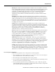
Port Adapter Locations on the VIP2 and in the Cisco 7200 Series Routers Figure 2 Two Port Adapters on a VIP2-15 or VIP2-40 (Horizontal Orientation Shown) Bus connector CPU Boot ROM U6 SRAM DIMM U5 U4 DRAM SIMMs U2 Port adapter in slot 1 H6448 Port adapter in slot 0 Figure 3 Two Port Adapters on a VIP2-50 (Horizontal Orientation Shown) Boot ROM CPU Bus connector SRAM daughter card DRAM DIMM Port adapter in slot 1 H10447 Port adapter in slot 0 Note In the Cisco 7000, Cisco 7507, and Cisco
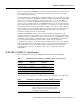
What Is the 5EFL Port Adapter? Figure 4 Port Adapters in the Cisco 7206 Port adapter slot 6 Port adapter slot 4 Port adapter slot 2 Blank port adapter 3 2 1 0 6 TOKEN RING 5 FAST ETHERNET 4 RJ4 5 MII 0 LIN K D LE AB EN 0 1 TX 2 RX 4 TX RX 3 TX RX 2 TX RX TX EN ETHERNET-10BFL CD LB RC RD TC TD CD LB RC RD TC TD CD LB RC RD TC TD CD LB RC RD TC TD EN FAST SERIAL RX 3 3 2 2 1 0 LINK 1 0 3 EN AB LE D ETHERNET 10BT ET ES R PU 0 D LE AB 5 O P
5EFL Port Adapter Multimode Fiber-Optic Cable and Receptacles 5EFL Port Adapter Multimode Fiber-Optic Cable and Receptacles The interface connectors on the 5EFL port adapter are five pairs of (ST) receptacles, designated as RX and TX. You can use all five connection pairs simultaneously or any combination of each pair individually. Each connection pair supports IEEE 802.3 and Ethernet 10BASE-FL interfaces compliant with appropriate standards.
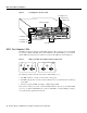
VIP2 and the 5EFL Port Adapter Figure 7 VIP2-15 or VIP2-40 with Two 5EFL Port Adapter Installed (Horizontal Orientation Shown) CPU Bus connector Boot ROM U6 SRAM DIMM U5 U4 DRAM SIMMs U2 Port adapter slot 1 Port adapter slot 0 X X TX R X TX R X TX R X TX R ETHERNET-10BFL N E TX R X X TX R 4 3 2 1 0 TX R X TX R X X TX R TX R 4 3 2 1 0 H6472 ETHERNET-10BFL N E Port adapter handles not shown Note Port adapters have a handle attached, but this handle is
Installing or Replacing a Port Adapter on a VIP2 Installing or Replacing a Port Adapter on a VIP2 This section provides the standard procedures for installing or replacing a port adapter on the VIP2. Depending on the circumstances, you might need to install a new port adapter on a VIP2 motherboard or replace a failed port adapter in the field.
VIP2 and the 5EFL Port Adapter Location of Port Adapter Screw (Partial Port Adapter View) H3148 Figure 9 Screw Step 6 Remove the screw that secures the port adapter (or blank port adapter). Step 7 With the screw removed, grasp the handle on the front of the port adapter (or blank port adapter) and carefully pull it out of its slot, away from the edge connector at the rear of the slot. (See Figure 10.
Installing or Replacing a Port Adapter on a VIP2 Step 9 Remove the new port adapter from its antistatic container and position it at the opening of the slot. (See Figure 11.) Step 10 Carefully align the port adapter carrier between the upper and lower edges of the port adapter slot, as shown in Figure 11.
VIP2 and the 5EFL Port Adapter Step 11 Port Adapter Installed in a Port Adapter Slot (Partial Port Adapter View) H3152 Figure 12 Carefully slide the new port adapter into the port adapter slot until the connector on the port adapter is completely mated with the connector on the motherboard. Step 12 Replace the screw in the rear of the port adapter slot. (See Figure 9 for its location.) Do not overtighten this screw. Step 13 Reinstall the VIP2 in the system.
Attaching 5EFL Port Adapter Interface Cables Attaching 5EFL Port Adapter Interface Cables On a single 5EFL port adapter, you can use up to five pairs of ST fiber-optic connections. The 5EFL port adapter is an end station device and not a repeater. You must connect the 5EFL port adapter to a 10BASE-FL repeater or hub. ST-type fiber-optic cables are not available from Cisco Systems; they are available from outside commercial cable vendors.
VIP2 and the 5EFL Port Adapter After you verify that the new 5EFL port adapter is installed correctly (the enabled LED goes on), use the privileged-level configure command to configure the new interfaces. Be prepared with the information you will need, such as the following: • • • Protocols you plan to route on each new interface. Internet protocol (IP) addresses if you plan to configure the interfaces for IP routing. Whether the new interfaces will use bridging.
Configuring the 5EFL Interfaces Note If you remove the 5EFL-equipped VIP2 from slot 3 and install it in slot 2, the addresses of those same 10BASE-FL ports become 2/0/0 through 2/0/4 and 2/1/0 through 2/1/4.
VIP2 and the 5EFL Port Adapter Step 3 If IP routing is enabled on the system, you can assign an IP address and subnet mask to the interface with the ip address configuration subcommand, as in the following example: Router(config-int)# ip address 1.1.1.10 255.255.255.0 Step 4 Add any additional configuration subcommands required to enable routing protocols and set the interface characteristics.
Configuring the 5EFL Interfaces Using show Commands to Display Interface Information To display information about a specific interface, use the show interfaces command with the interface type and port address in the format show interfaces [type slot/port adapter/port]. Following is an example of how the show interfaces [type slot/port adapter/port] command displays status information (including the physical slot and port address) for the interfaces you specify.
VIP2 and the 5EFL Port Adapter The following example of the show interfaces ethernet slot/port adapter/port command shows all of the information specific to the first 5EFL interface port (interface port 0) in chassis slot 3, port adapter slot 1: Router# sh int e 3/1/0 Ethernet3/1/0 is administratively down, line protocol is down Hardware is cyBus Ethernet, address is 0000.0ca5.2305 (bia 0000.0ca5.
Configuring the 5EFL Interfaces The show version (or show hardware) command displays the configuration of the system hardware (the number of each interface processor type installed), the software version, the names and sources of configuration files, and the boot images. Following is an example of the show version command used with a Cisco 7500 series system: Router# show version Cisco Internetwork Operating System Software IOS (tm) GS Software (RSP-A), Version 11.
VIP2 and the 5EFL Port Adapter To determine which type of port adapter is installed on a VIP2 in your system, use the show diag slot command. Specific port adapter information is displayed, as shown in the following example of a 5EFL port adapter in chassis slot 1: Router# show diag 1 Slot 1: Physical slot 1, ~physical slot 0xE, logical slot 1, CBus 0 Microcode Status 0xC Master Enable, LED, WCS Loaded Board is analyzed Pending I/O Status: Console I/O EEPROM format version 1 VIP2 controller, HW rev 2.
Cisco 7200 Series and the 5EFL Port Adapter Cisco 7200 Series and the 5EFL Port Adapter The 5EFL port adapter is used in the Cisco 7200 series routers and can be installed in any of the available port adapter slots. Figure 15 shows a Cisco 7206 with a 5EFL port adapter installed in port adapter slot 2.
Cisco 7200 Series and the 5EFL Port Adapter Installing or Replacing a Port Adapter in Cisco 7200 Series Routers This section provides the standard procedures for installing or replacing port adapters in a Cisco 7200 series router. Depending on your circumstances, you might need to install a new port adapter in a Cisco 7200 series router or replace a failed port adapter in the field.
Installing or Replacing a Port Adapter in Cisco 7200 Series Routers Grasp the handle on the port adapter and pull the port adapter from the midplane, about halfway out of its slot. If you are removing a blank port adapter, pull the blank port adapter from the port adapter slot. Step 3 Note As you disengage the port adapter from the router midplane, OIR administratively shuts down all active interfaces on the port adapter.
Cisco 7200 Series and the 5EFL Port Adapter Replacing a Port Adapter Use the following standard procedure to install a new port adapter in a Cisco 7200 series router: Step 1 Attach an ESD-preventative wrist strap between you and an unfinished chassis surface. Step 2 Use both hands to grasp the port adapter by its metal carrier edges and position the port adapter so that its components are downward. (Refer to Figure 17).
Installing or Replacing a Port Adapter in Cisco 7200 Series Routers Step 7 Move the port adapter lever to the locked position. Figure 19 shows the port adapter lever in the locked position. Note If the port adapter lever does not move to the locked position, the port adapter is not completely seated in the midplane. Carefully pull the port adapter halfway out of the slot, reinsert it, and move the port adapter lever to the locked position.
Cisco 7200 Series and the 5EFL Port Adapter Attaching 5EFL Port Adapter Interface Cables On a single 5EFL port adapter, you can use up to five pairs of ST fiber-optic connections. The 5EFL port adapter is an end station device and not a repeater; you must connect the 5EFL port adapter to a 10BASE-FL repeater or hub. ST-type fiber-optic cables are not available from Cisco Systems; they are available from outside commercial cable vendors.
Configuring the 5EFL Interfaces Configuring the 5EFL Interfaces If you installed a new 5EFL port adapter or if you want to change the configuration of an existing interface, you must enter configuration mode using the configure command. If you replaced a 5EFL port adapter that was previously configured, the system will recognize the new 5EFL interfaces and bring them up in their existing configuration.
Cisco 7200 Series and the 5EFL Port Adapter Figure 21 shows the port adapter slots and interface ports of a Cisco 7206. The port adapter slot numbers start with 1 and continue through 6 (slot 0 is always reserved for the Fast Ethernet port on the I/O controller—if present). The individual interface port numbers always begin with 0. The number of additional ports depends on the number of ports on a port adapter.
Configuring the 5EFL Interfaces Step 2 At the prompt, specify the first interface to configure by entering the subcommand interface, followed by the type (ethernet) and slot/interface (port adapter slot number and interface number).
Cisco 7200 Series and the 5EFL Port Adapter Step 5 Display the running configuration file with the show running-config command. Display the configuration stored in NVRAM using the show startup-config command. Verify that the configuration is accurate for the system and each interface. If the interface is down and you configured it as up, or if the displays indicate that the hardware is not functioning properly, ensure that the network interface is properly connected and terminated.
Configuring the 5EFL Interfaces The following example of the show interfaces ethernet slot/port command shows all of the information specific to the first 5EFL interface port (interface port 0) in port adapter slot 2: Router# sh int e 2/0 Ethernet2/0 is administratively down, line protocol is down Hardware is AmdP2 Ethernet, address is 1.1.1.10 (bia 0000.0ca5.
Cisco 7200 Series and the 5EFL Port Adapter To determine which type of port adapter is installed in your Cisco 7206, use the show diag slot command. Specific port adapter information is displayed, as shown in the following example of a 5EFL port adapter in chassis slot 2: Slot 2: Ethernet port adapter, 5 ports Port adapter is analyzed Port adapter insertion time 2d09h ago Hardware revision 1.
Configuring the 5EFL Interfaces For complete descriptions of interface subcommands and the configuration options available for Cisco 7200 series-related interfaces and functionality, refer to the publications listed in the section “If You Need More Information” on page 2.
Cisco Connection Online Cisco Connection Online Cisco Connection Online (CCO) is Cisco Systems’ primary, real-time support channel. Maintenance customers and partners can self-register on CCO to obtain additional information and services. Available 24 hours a day, 7 days a week, CCO provides a wealth of standard and value-added services to Cisco’s customers and business partners.
Documentation CD-ROM This document is to be used in conjunction with the documents listed in the “If You Need More Information” section.
Documentation CD-ROM 40 PA-5EFL Ethernet 10BASE-FL Port Adapter Installation and Configuration