
Network Router User Manual


3-19
Cisco 2600 Series Routers Hardware Installation Guide
OL-2171-06
Chapter 3 Installing the Router
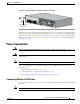
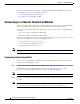
Connecting WAN, LAN, and Voice Cables
LAN, WAN, and Voice Connection Procedures
Connect each WAN, LAN, and voice cable to the appropriate connector on the chassis or on a network
module or interface card.
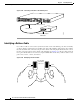
• Position the cables carefully, so that they do not put strain on the connectors.
• Organize cables in bundles such that cables do not intertwine.
• Inspect the cables to make sure that the routing and bend radiuses are satisfactory. Reposition
cables, if necessary.
• Install cable ties in accordance with site requirements.
For cable pinouts, refer to the online document Cisco Modular Access Router Cable Specifications.
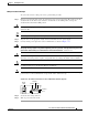
T1 digital voice RJ-48C/CA81A, tan Digital PBX RJ-48 T1 cable
Analog voice FXS RJ-11, gray Telephone, fax RJ-11
Analog voice FXO RJ-11, pink Central office, analog PBX RJ-11
Analog voice E&M RJ-11, brown Analog PBX RJ-11
BRI S/T WAN
(external NT1)
RJ-48C/CA81A,
orange
NT1 device or private integrated
network exchange (PINX)
RJ-48
BRI U WAN
(built-in NT1)
RJ-49C/CA11A, red ISDN network RJ-49
CT1/PRI T1 External T1 CSU DB-15 T1 serial cable
CT1/PRI-CSU T1 RJ-48C/CA81A interface RJ-48 straight-through
CE1/PRI E1 E1 network DB-15 to BNC, DB-15 to DB-15,
DB-15 to twinax, or DB-15 to RJ-45
Token Ring UTP, purple
STP, purple
Token Ring device RJ-45 Token Ring cable
56/64-kbps DSU/CSU 8-pin modular, blue RJ-48S interface RJ-48 straight-through
1. Refer to the Cisco Modular Access Router Cable Specifications for information about selecting these cables.
Table 3-2 WAN, LAN, and Voice Connections (continued)
Port or Connection Port Type, Color Connected To: Cable