
Network Router User Manual


3-15
Cisco 2600 Series Routers Hardware Installation Guide
OL-2171-06
Chapter 3 Installing the Router
Power Connections
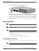
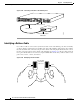
Figure 3-21 Ground Connection Using Ring Terminal, Cisco 2691
After the router has been installed and properly grounded, you can connect the power wiring; the WAN,
LAN, and voice cables; and the cables for administrative access, as required for your installation. For
cable connection procedures, see the “Power Connections” section on page 3-15, the “Connecting WAN,
LAN, and Voice Cables” section on page 3-18, and the “Connecting to a Console Terminal or Modem”
section on page 3-20.
Power Connections
Warning
Read the installation instructions before connecting the system to the power source.
Statement 1004
Warning
Do not work on the system, or connect or disconnect cables during periods of lightning activity.
Statement 1001
Note The installation must comply with all required electrical codes applicable at the installation site.
This section explains how to connect AC or DC power to Cisco 2600 series routers. It covers the
following topics:
• Connecting Routers to AC Power, page 3-15
• Connecting Routers to a DC-Input Power Supply, page 3-16
• Connecting Routers to the Cisco Redundant Power System, page 3-18
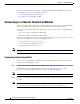
Connecting Routers to AC Power
If your router uses AC power, connect it to a 15 A, 120 VAC (10 A, 240 VAC) circuit with overcurrent
protection.
Note The input voltage tolerance limits for AC power are 85 and 264 VAC.
Ring terminal
attachment
103008
EN
A
S
Y
N
C
AS
YN
C 8-15
A
SYN
C 0-7
1
5
1
4
1
3
1
2
1
1
1
0
9
8
7
6
5
4
3
2
1
0
ASY
NC
24-31
ASY
NC
16-23
3
1
3
0
2
9
2
8
2
7
2
6
2
5
2
4
2
3
2
2
2
1
2
0
1
9
1
8
1
7
1
6
S
E
E
M
A
N
U
A
L
B
E
F
O
R
E
IN
S
T
A
L
L
A
T
IO
N
C
O
N
S
O
L
E
A
U
X
F
A
S
T
E
T
H
E
R
N
E
T
0/
1
F
A
S
T
E
T
H
E
R
N
E
T
0
/0
AL
CD
LP
RD
TD
S
E
E
M
A
N
U
A
L
B
E
F
O
R
E
IN
S
T
A
L
L
A
T
I
O
N
D
S
U
56
K
AL
CD
LP
RD
TD
S
E
E
M
A
N
U
A
L
B
E
F
O
R
E
IN
S
TA
L
L
A
T
IO
N
D
S
U
56
K
A
C
T
1
00 M
bp
s
LINK
ACT
100
M
b
ps
L
IN
K
C
F1
CISCO2691