
User's Manual
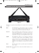


The Router’s rear panel (as shown in Figure 1-1) is where all of its connections
are made.
WA N The WAN (Wide Area Network) Port is where you will con-
nect your cable or DSL modem with an Ethernet cable. Your
modem connection will not work from any other port.
Ports 1-4 These four LAN (Local Area Network) ports are where you
will connect networked devices, such as PCs, print servers,
and any other Ethernet devices you want to put on your net-
work. If Port 4 is being used, the Uplink Port will not work.
Uplink The Uplink Port is where you can expand your network by
connecting to another switch or hub. Uplinking to another
switch or a hub is done by simply running a cable from the
Uplink Port to the other device. The Uplink Port is shared
with Port 4. If the Uplink port is being used, Port 4 will not
work.
Power The Power Port is where you will connect the included AC
Power adapter.
Antenna Jacks The Antenna Jacks are where the included antennas are con-
nected.
Figure 1-1
The Wireless Access Point Router’s Ports
Instant Wireless
TM
Series
5
BEFW11S4 VER 3 USER GUIDE_2nd.qxd 10/15/02 10:33 AM Page 4