USB/IGBASE-T Ethernet Adapter FCC Compliance Statement This device complies with Part 15 of the FCC rules. Operation is subject 10 the following two conditions: {1) this device may not cause harmful interference, and (2) this device must accept any interference received, including interference that may cause desired operation. NOTE This equipment has been tested and found to comply with the limits for a Class B digital device, pursuant to Part 15 of the FCC rules.
USB/IOBASE-T Ethernet Adapter Reorient of relocate the receiving antenna. Increase ihe separation between the equipment and receiver. Connect the equipment into an outlet on a circuit different from that to which the receiver is connected. Consult the dealer of sn experienced radio / TV technician for help. CE Compliance Statement We hereby certify that the Ethernet transceiver complies with the EN 50081-1 sad EN 50082.1 requirements.
USB/I0BASE-T Ethernet Adapter CONTENTS FCC Compliance Statement oe 1 CE Compliance Statement Introduction Summary of Features Package Contents LED Indicators USB Cable Network Driver oe Installing the Transceiver cnn 7 Specifications eversvrrsumvenns §
SUBBASEMENT-T Ethernet Ada pier Section 1 Introduction The 10Mbps Ethernet Adapter is designed for a convenience way to connects your PC 10 the BASSET network vie the USB (Universal Serial Bus) interface. The device is quipped with a Typo-B receptacle for connection 10 the USB host or bub, and a RI.45 receptacle tn the ABASE-T Ethernet network. The bus-supplied power design can easily provide an operating power to the adapter, no external power supply is required.
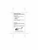
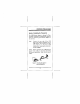
SUBBASEMENT-T Ethernet Adapter Package Contents The package should contain the following items: u USB/ Ethernet adapter 1 User's manual 1 USB cable C Driver diskette 1f any item is missing or damaged, please contact your dealer for a replacement LED Indicators Your USB dapperer provides the variety of informs. rive LED on the up panel for cays viewing and troubleshooting. This section will help you to understand the LED indication, Figure 1-1 show the up view of the adapter.
USB/1OBASE-T Ethernet Adapter LACTATION LED The green LED displays the link end activity status, If 8 good link is established on tbe port, this green LED will be continuously lit, indicating 2 valid network between the network node and the transceiver. When data is transmitted or received, the green LED will flash. USB LED The green LED displays the USB interface connection status. IT a valid connection is detected via the USB interface and the driver is initialized property, the green LED will be fit.
USB/OBASE-T Ethernet Adapter for different Network Operating Systems. Far more information about the driver installation, refer to the READMITTED which is located in the corresponding driver subcategory.
USB/IOBASE-T Ethernet Adapter Section 2 Installing the Transceiver The USB/Ethernet adapter is design for Plug. and-Play installation, performing the stops as below (o connecting your Ethernet adapter to the network Step] Connect the one end of the USB cable to the Type-B receptacle of the USB speedster, and connect the either end (Type-A) to the PC's USB interface port, ensuring the connectors are fully engaged.
USB/10BASE-T Ethernet Adapter Step? Connecting UTP cable Connect one end of a twisted-pair cable to the USB adapter's RI-45 port, and the other end to an appropriate device with a 10 Bps Ethernet interface.
USB/10BASE-T Ethernet Adapter Section 3 Specifications IEEE 802.