
User Manual


EP7309/11/12 User’s Manual - DS508UM4 16-9
Copyright Cirrus Logic, Inc. 2003
DAI/CODEC/SSI2
1616
16
item that has been p opped to the top of the FIFO will be invalid and should be
ignored. In this case, the correct byte will have been stored in the most significant byte
of th e next half-word to be clocked into th e FIFO.
Note: All the writes/reads to the FIFO are done word at a time (data on the lower 16
bits is valid and upper 16 bits are i gnored). Software manually pops the residual
byte into the RX FIFO by writing to the SS2POP location (the value written is
ignored). This write will strobe the RX FIFO write signal, causing the residual
byte to be written into the FIFO.
Support for Asymmetric Traffic
The interface supports asym metric traffic (i.e., unbalanced data flow). This is
accomplished through separate transmit and receive frame sync control lines. In
operation, the receiving node receives a byte of data on the eight clocks following the
assertion of the receive frame sync control line. In a similar fashion, the sending node
can transmit a byte of data on the eight clocks following the assertion of the transmit
frame sync pulse. There is no correlation in the frequency of assertions of the RX and
TX frame sync control lines (
SSITXFR and SSIRXFR). Hence, the R X path may bear a
greater data throughput than the TX p ath, or vice versa. Both directions, however,
have an absolute maximum data throughput rate determined by the maximum
possible clock frequency, assuming that the interrupt response of the target OS is
sufficiently quick.
Continuous Data Transfer
Data by tes may be sent/received in a contiguous man ner without interleaving clocks
between bytes. The frame sync control l ine(s) are ei ght clocks apart and aligned with
the clock representing bit D0 of the preceding byte ( i.e., one bit in advance of the
MSB).
Discontinuous Clock
In order to save power du ring the idle times, the clock line is put i nto a static low
state. The master is responsible for putting the link into the Idle State. Th e Idle State
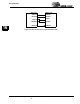
Figure 16-4. Residual Byte Reading
00
11
01
Residual bit valid
New RX byte received
Pop FIFO
New RX byte
received