
User Manual


EP7309/11/12 User’s Manual - DS508UM4 12-1
Copyright Cirrus Logic, Inc. 2003
1212
12
Chapter 12
12PWM Interface
Introduction
There are two PW M (Pulse Width Modulator) outputs. This was designed for DC to
DC conversion circuits bu t can be used for other type s of controls. Typical use
includes backlight voltage for LCDs and programmable LCD contrast voltages.
Features
• Operates from Internal PLL or external 13 MH z clock
• Programmable duty cycle
• Feedback circuit control
• Power monitor for external AC or b attery use
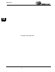
Block Diagram
The block diagram below illustrates a typical design using both PWM drives in a
power supply.
V-
V+
+
-
VDD
FB1
V-
V+
+
-
VDD
FB0
V+
Vref
Vref
Comparator
Comparator
DC-DC Circuit
PWM Drive0
PWM Drive1
0V
0V
V-
10K
10K
VDD
GND
10K
10K
Figure 12-1. Block Diagram of a Power Supply Using Two PWM Drives